Guide vane ring for a turbomachine

a technology of turbomachines and guide vane rings, which is applied in the direction of turbines, machines/engines, manufacturing tools, etc., can solve the problems of guide vane rings that cannot withstand the resulting thermal loads without further action, and the guide vane rings thereby have leakage, etc., to achieve cost-effective, cost-effective and simple manner, and easy construction.

Inactive Publication Date: 2016-08-04
MTU AERO ENGINES GMBH
View PDF16 Cites 21 Cited by
  • Summary
  • Abstract
  • Description
  • Claims
  • Application Information

AI Technical Summary

Benefits of technology

[0007]A first aspect of the invention relates to a guide vane ring for a turbomachine with at least one guide vane ring segment comprising at least one guide vane arranged radially around an axis of rotation, an outer shroud arranged radially on the outer side of the guide vane, and an inner shroud arranged radially on the inner side of the guide vane, with the outer shroud or the inner shroud having at least one expansion joint. In addition, the guide vane ring segment with the guide vane, the outer shroud, and the inner shroud are formed in one piece, with the at least one expansion joint being sealed by means of at least one sealing device arranged in the expansion joint. A one-piece guide vane ring segment may also be referred to as an integral guide vane ring segment. The sealing device in the expansion joint brings about an especially high efficiency of the guide vane ring, because, as a result thereof, no leakage or at least only a particularly reduced leakage will occur at the expansion joint or expansion joints of the guide vane ring segments. As a result, an integral guide vane ring segment can also be employed for especially large turbomachines and / or turbomachines with especially high operating temperatures, without the efficiency of the guide vane ring being reduced on account of the expansion joints that are then necessary.
[0025]It is possible by means of the method according to the invention for the additive manufacture of a guide vane ring to produce the guide vane ring according to the first aspect of the invention in an especially cost-effective manner. The guide vane ring according to the invention can be manufactured as an integral guide vane ring in one piece in a single manufacturing step. This means that all components of the guide vane ring are fabricated directly in a single process step in a cost-effective and rapid manner. In particular, the additive method can be an additive manufacturing method such as selective laser sintering or selective laser melting.

Problems solved by technology

A drawback is that, for especially large dimensions and / or high operating temperatures of the turbomachine, such a guide vane ring cannot withstand the resulting thermal loads without anything further.
However, a drawback of such expansion joints is that the guide vane ring thereby has leakage.
However, these expansion joints do not pass through the entire inner shroud in the peripheral direction, so that high loads can continue to act on the inner shroud.

Method used


Image

  • Guide vane ring for a turbomachine
  • Guide vane ring for a turbomachine

Examples


Embodiment Construction

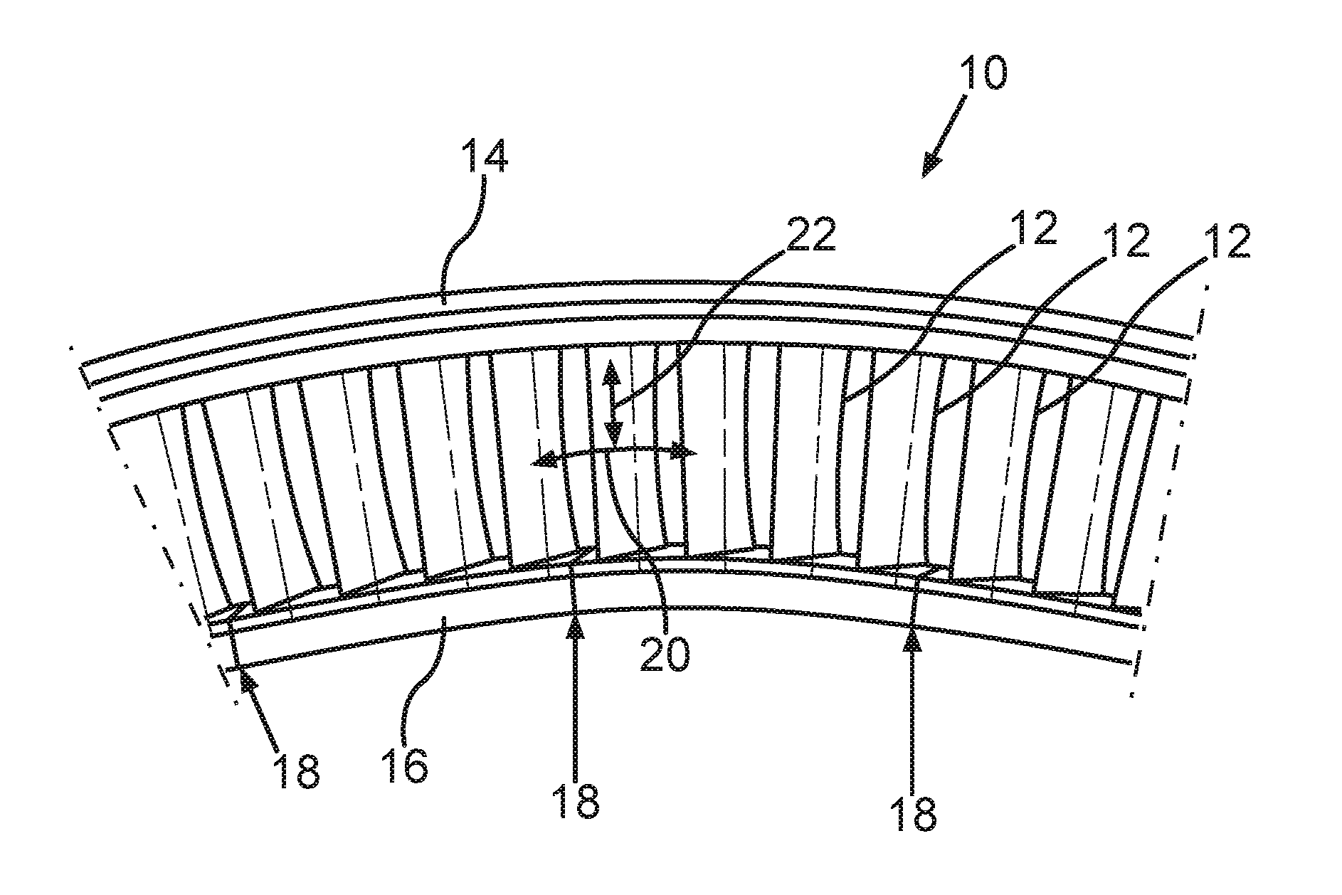
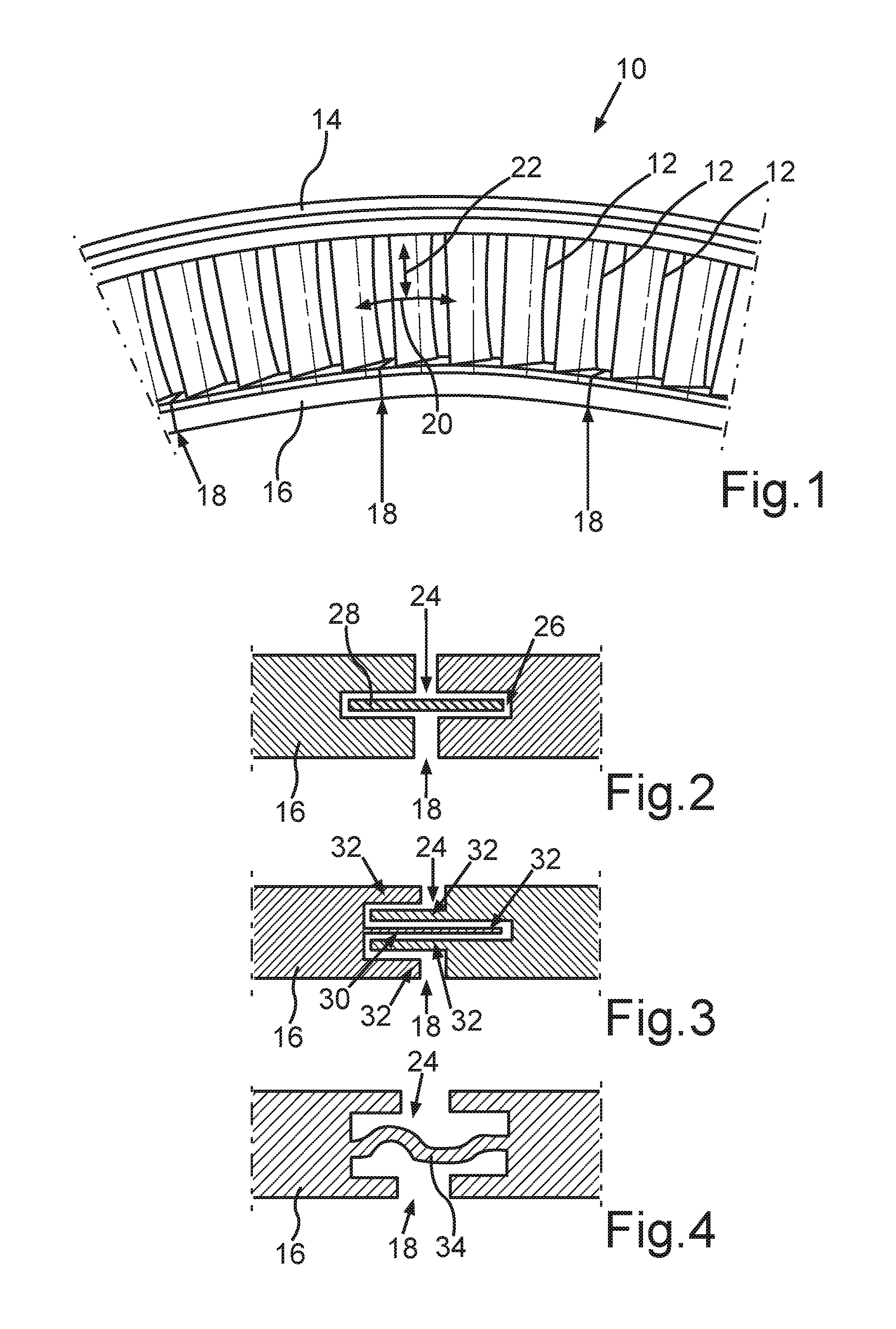
[0033]FIG. 1 shows, in an excerpted schematic view, a guide vane ring 10 for a turbomachine. The turbomachine can be a gas turbine, for example, in particular an aircraft engine. This guide vane ring 10 comprises a plurality of guide vanes 12 arranged radially around an axis of rotation. The radial direction is marked by arrow 22. By means of these guide vanes 12, a flow of gas, which flows through the turbomachine, can be influenced. In particular, the flow of gas can be diverted by means of the guide vane ring 10 and / or vortexes in the flow of gas can be reduced. In this way, the efficiency of the turbomachine is increased. The guide vane ring 10 can be arranged, for example, in front of or in back of a rotor blade ring of a turbine or a compressor of the turbomachine.

[0034]In the exemplary embodiment shown in FIG. 1, the guide vane ring 10 comprises only a single guide vane ring segment running 360° around the axis of rotation. In this way, no leakage between different guide vane...


PUM

PropertyMeasurementUnit
operating temperaturesaaaaaaaaaa
thermal expansionaaaaaaaaaa
thermal loadaaaaaaaaaa

Abstract

The invention relates to a guide vane ring (10) with at least one guide vane ring segment for a turbomachine, including a plurality of guide vanes (12) arranged radially around an axis of rotation, an outer shroud (14) arranged radially on the outer side of the guide vanes (12), and an inner shroud (16) arranged radially on the inner side of the guide vanes (12), wherein the outer shroud (14) or the inner shroud (16) has at least one expansion joint (18), wherein the guide vane ring segment is formed in one piece with the guide vanes (12), the outer shroud (14), and the inner shroud (16) and the at least one expansion joint (18) is sealed in each case by at least one sealing device (24) arranged in the respective expansion joint (18).

Description

BACKGROUND OF THE INVENTION[0001]The invention relates to a guide vane ring for a turbomachine. The invention further relates to a gas turbine with such a guide vane ring and to a method for the manufacture of such a guide vane ring.[0002]Known from DE 10 2009 013 819 A1 is a guide vane ring for a turbomachine. This guide vane ring comprises a plurality of guide vanes arranged radially around an axis of rotation, by means of which a flow of gas can be diverted into a turbomachine. The guide vane ring comprises an outer shroud arranged radially on the outer side of the guide vanes and an inner shroud arranged radially on the inner side of the guide vanes. In this case, the guide vane ring is composed of a plurality of individual guide vane ring segments, which are welded together by means of a thermal joining method.[0003]A drawback is that, for especially large dimensions and / or high operating temperatures of the turbomachine, such a guide vane ring cannot withstand the resulting th...

Claims


Application Information

Patent Timeline
Patent Type & Authority Applications(United States)
IPC IPC(8): F01D9/04B23K26/342B22F3/105F01D25/00B22F5/04
CPCF01D9/04F01D11/005F05D2240/11F05D2240/55F05D2260/941F05D2230/31F01D25/005B33Y80/00B23K26/342B22F3/1055B22F5/04F01D9/047B33Y10/00Y02P10/25B22F10/28B22F10/25
Inventor LIEBL, CHRISTIANSCHARL, RICHARDKIRCHNER, DANIELBUCK, ALEXANDERHESS, THOMAS
Owner MTU AERO ENGINES GMBH
Why Eureka
Try Eureka