
Governor

a governor and pressure detector technology, applied in the direction of fluid pressure control, process and machine control, instruments, etc., can solve the problems of affecting the response of the governor, affecting the quality of the control system, so as to prevent the damage to connected parts and other such parts, and the effect of reducing the fluctuation of pressure in the secondary side channel

Inactive Publication Date: 2016-02-18
AZBIL KIMMON
View PDF0 Cites 0 Cited by
  • Summary
  • Abstract
  • Description
  • Claims
  • Application Information

AI Technical Summary

Benefits of technology

The present invention provides a non-return valve that prevents damage to connected parts and alleviates pressure fluctuation in the secondary side channel. This happens because the non-return valve is capable of passing fluid from the primary side channel to the pressure detection chamber, when the pressure in the primary side channel rapidly rises. The governor switches to a closed state within a short amount of time, thus preventing damage to connected parts and other such parts.

Problems solved by technology

Then, because the pressure in the pressure detector rapidly rises, the valve shuts, but because time passes until the high-pressure fluid passes through the secondary side channel and the adjusting tube and reaches the pressure detector, time also passes between the rapid rise of the pressure in the primary side channel and the shutting of the valve, and the response of the governor is therefore inferior.
In addition, because time passes until the valve shuts, a considerable amount of high-pressure fluid flows through the secondary side channel and adjusting tube to the pressure detector, and the pressure in the pressure detector sharply rises all at once.
As a result, when the pressure in the primary side channel rapidly rises, a large force impacts the parts involved in the valve shutting operation, thereby damaging said parts, and the pressure fluctuation in the primary side channel is accompanied by significant fluctuation also in the secondary side channel.

Method used


Image

  • Governor
  • Governor
  • Governor

Examples


embodiment 1

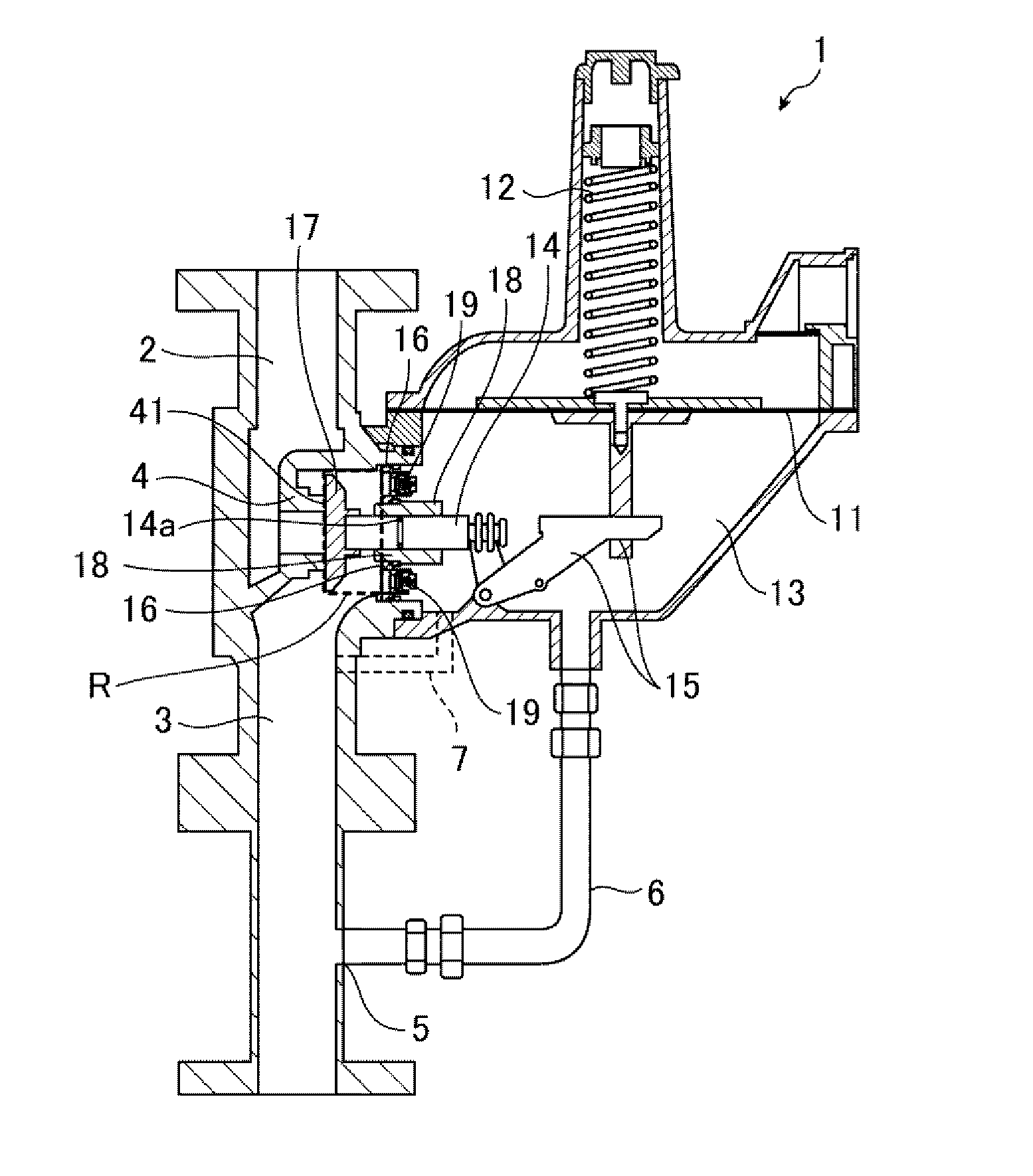
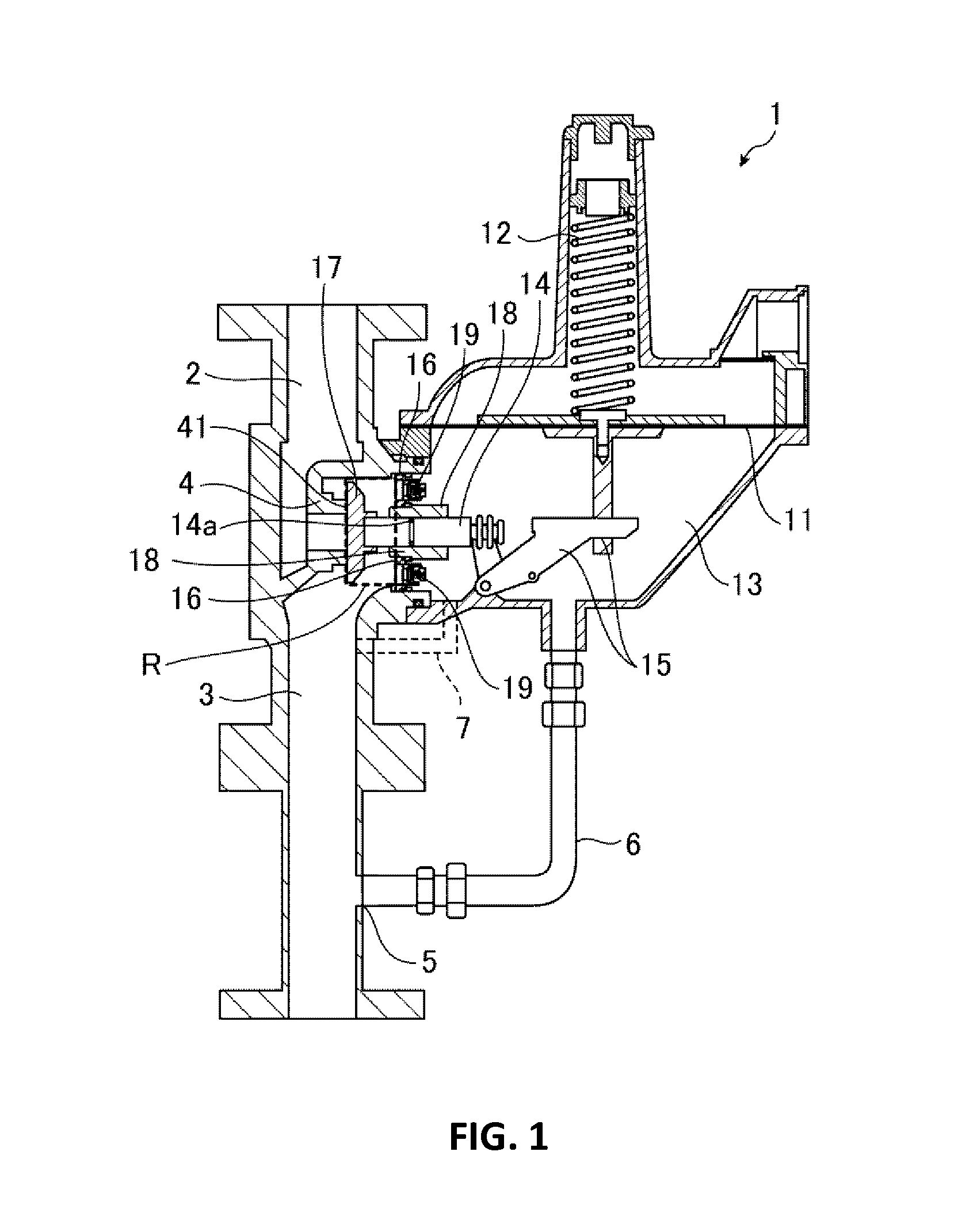
[0012]FIG. 1 is a cross-sectional view showing a governor 1 according to Embodiment 1 of the present invention. The governor 1 provided between a primary side channel 2 and a secondary side channel 3 opens and closes a port 4 positioned between the primary side channel 2 and the secondary side channel 3, and while adjusting the pressure in the secondary side channel 3, it causes fluid (for example, gasoline) to flow from the primary side channel 2 to the secondary side channel 3. The governor 1 has inside it a diaphragm 11, whose circumferential edge is fixed, and a spring 12 is provided in one space (the upper side on the page) partitioned by the diaphragm 11, and a pressure detection chamber 13 is formed in the other space (the lower side on the page). The pressure detection chamber 13 is connected to the secondary side channel 3 via an adjusting tube 6 (illustrated as a plan view), which connects with the secondary side channel 3 at the connection 5, and is capable of conducting ...


PUM


Abstract

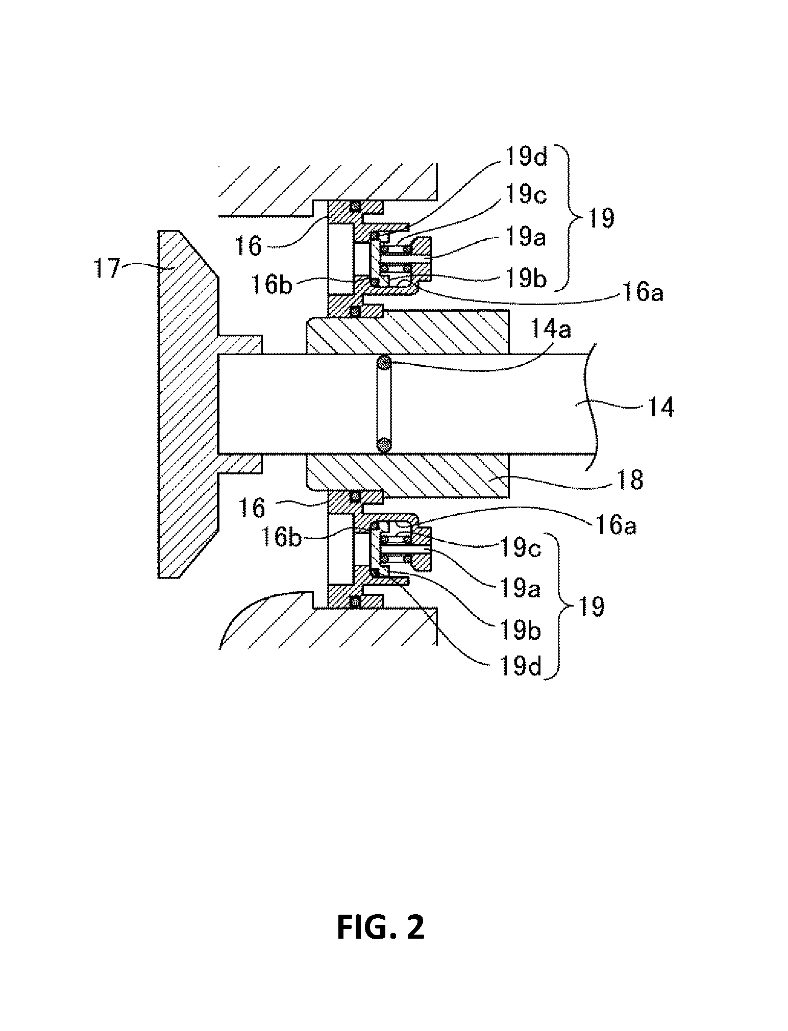
[Problem(s)] To provide a governor capable of preventing damage to parts when the pressure in the primary side channel rapidly rises, and of alleviating pressure fluctuation in the secondary side channel.[Solution] A governor 1 is provided with a non-return valve 19 at a shield plate 16 such that when the pressure in the primary side channel 2 rapidly rises, the fluid from the primary side channel 2, which has passed through the port 4, can immediately flow into the pressure detection chamber 13 through the non-return valve 19. As a result, when the pressure in the primary side channel 2 rapidly rises, the governor 1 is capable of entering a closed valve state within a short amount of time.

Description

CROSS REFERENCE TO RELATED APPLICATION[0001]The present application claims the benefit of and priority to Japanese Patent Application No. 2014-164392, filed on Aug. 12, 2014, the entire contents of which is incorporated herein by reference.TECHNICAL FIELD[0002]The present invention pertains to a governor provided between a primary side channel and a secondary side channel to circulate fluid from the primary side channel to the secondary side channel while adjusting the pressure in the secondary side channel.PRIOR ART[0003]To circulate fluid while adjusting the fluid pressure, a diaphragm governor is installed at the connection between the primary side piping (primary side channel) and the secondary side piping (secondary side channel). See, for example, Patent Document 1. A diaphragm governor is configured such that a valve is interlocked with a diaphragm that is displaced according to the pressure in the secondary side channel, which is detected by a pressure detector, and when the...

Claims


Application Information

Patent Timeline
Patent Type & Authority Applications(United States)
IPC IPC(8): F16K17/02F16K1/52F16K31/126
CPCF16K17/02F16K31/126F16K1/526G05D16/02G05D16/0683
Inventor KOBAYASHI, TOMOYUKI
Owner AZBIL KIMMON
Learn More