Injector with a magnet valve for controlling an injection valve

a magnet valve and injection valve technology, applied in the field of injectors, can solve problems such as delay in the closure of the nozzle needle, and achieve the effects of less variation in the injection quantity, improved engine noise and emissions values, and improved engine performance values

Inactive Publication Date: 2005-04-12
ROBERT BOSCH GMBH
View PDF9 Cites 15 Cited by
  • Summary
  • Abstract
  • Description
  • Claims
  • Application Information

AI Technical Summary

Benefits of technology

The injector of the invention has means for reducing pressure fluctuations that occur in the lower armature chamber. It has in fact been demonstrated that pressure surges in the lower armature chamber, which through the bore in the armature guide act directly on the armature face, cause the armature to lift from the valve seat and thus result in a delayed closure of the nozzle needle. By reducing the pressure fluctuations in the lower armature chamber, the armature recoil can therefore be reduced to a minimum, and thus a continuous closure of the nozzle needle can be assured.
The intensity of the armature recoil depends in fact on the return counterpressure (the pressure of the fuel quantities returned via the return bore), which for reasons of system requirements falls within a certain range of variation. Because of the reduction of pressure fluctuations in the lower armature chamber that is achieved according to the invention, pressure fluctuations propagating from the return bore into the lower armature chamber can therefore be compensated for, and thus the intensity of the armature recoil can be reduced sharply.
The means for reducing pressure fluctuations in the lower armature chamber can include recesses or built-in components to be machined into it, by means of which an increased volume of the return bore and / or of the lower armature chamber is achieved. In general, certain portions, affected by the return of the fuel quantities, in both the magnet valve and the injection valve can be embodied with an increased volume. Such an increase in volume brings about a reduction in the pressure and thus a lessening of pressure surges.
The invention leads to a course of the armature stroke which is severely damped, compared to the course in known magnet valves, so that armature recoil is hardly noticeable any longer. Accordingly the course of the needle stroke of the nozzle needle is continuous, so that the nozzle needle moves without delay, continuously, into its closing position. This improves the noise and emissions values of the engine. Moreover, the injection quantity no longer varies as a function of the return counterpressure and as a result the performance values of the engine are improved along with its noise and emissions values.
The undefined recoil of the armature and thus the undefined closure of the nozzle needle, in the prior art, cause a major variation in the injection quantity from one stroke to another. The continuous closure of the nozzle needle achieved by means of the invention thus brings about less variation in the injection quantity from stroke to stroke. Finally, for reasons of emissions and noise, there is also a need to be able to provide a plurality of injections in rapid succession. This is possible only if the armature does not recoil further, or comes quickly to a stop. By means of the invention, the spacing between successive injections can be shortened, since the nozzle needle moves continuously into its closing position without delay.

Problems solved by technology

It has in fact been demonstrated that pressure surges in the lower armature chamber, which through the bore in the armature guide act directly on the armature face, cause the armature to lift from the valve seat and thus result in a delayed closure of the nozzle needle.

Method used


Image

  • Injector with a magnet valve for controlling an injection valve
  • Injector with a magnet valve for controlling an injection valve
  • Injector with a magnet valve for controlling an injection valve

Examples


Embodiment Construction

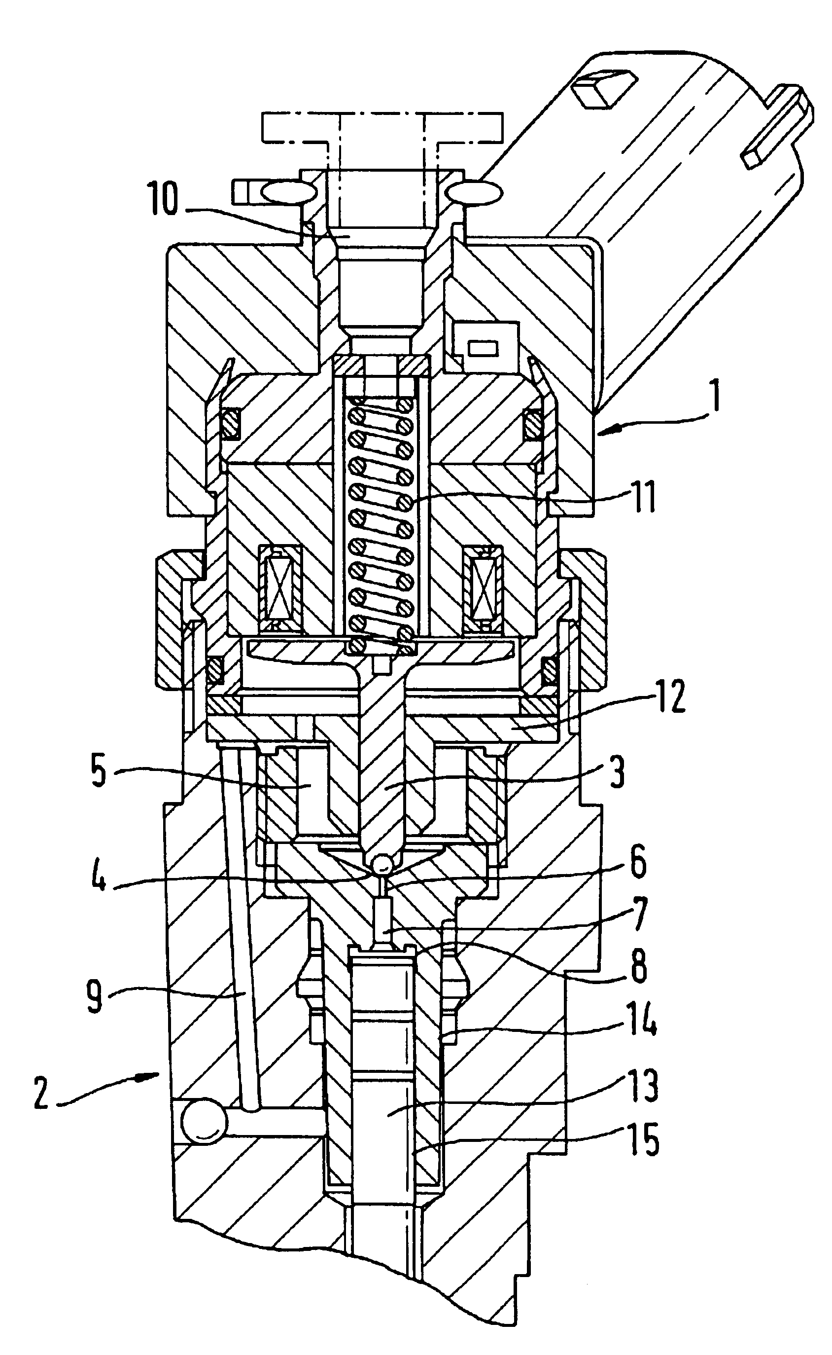
FIG. 1 shows the usual design of an injector, of the kind used particularly for fuel injection in common rail systems, comprising a magnet valve 1 and an injection valve 2. In the sketch, only the parts of the injector that are essential to the invention are identified by reference numeral. The one-piece armature 3 is drawn upward, counter to the spring force of the armature spring 11 as a result of supplying current to the magnet valve 1. The armature 3 travels in the armature guide 12, and when no current is supplied to the magnet valve 1, the armature rests on the valve seat 4 of the injection valve 2. In this state, the fluid communication is interrupted with the control pressure chamber 8 of the injection valve 2 by closing off the outlet throttle 6 and the bore 7. When the magnet valve is supplied with current, conversely, the outlet throttle 6 opens, and the pressure in the control pressure chamber 8 drops, since fluid can now flow from the control pressure chamber 8 into the...


PUM


Abstract

Disclosed is an injector for fuel injection, with a magnet valve for controlling an injection valve, in which the magnet valve has a movable armature that can be moved onto a valve seat in the lower armature chamber. The lower armature chamber communicates fluidically with the control pressure chamber of the injection valve via bores. Via a return bore, incidental leak fuel quantities can be returned to a tank via the lower armature chamber. To prevent armature recoil upon closure of the valve seat by the armature, it is proposed that means be provided in the injector for reducing pressure fluctuations occurring in the lower armature chamber. Eliminating pressure fluctuations in the lower armature chamber leads to maximal elimination of armature recoil.

Description

BACKGROUND OF THE INVENTION1. Field of the InventionThe invention relates to an injector, in particular for fuel injection, with a magnet valve for controlling an injection valve. Such magnet valves are used to control an injection valve of a fuel injection system that has a nozzle needle whose opening and closing position are controllable by the magnet valve, so that injection bores can be opened to inject fuel.2. Description of the Prior ArtA known magnet valve has a movable armature, which when the magnet assembly of the magnet valve is supplied with electric current lifts from a valve seat in the lower armature chamber. This valve seat is in turn in fluidic communication with the control pressure chamber of the injection valve via one or more (throttle) bores. When the valve seat opens, the pressure in the control pressure chamber of the injection valve drops, and fluid (pressure medium) flows via the bores in the direction of the valve seat and from there into the lower armatur...

Claims


Application Information

Patent Timeline
Patent Type & Authority Patents(United States)
IPC IPC(8): F02M59/00F02M59/46F02M55/00F02M47/02F02M63/00F02M61/16F02M45/08F02M47/00F02M61/20
CPCF02M47/027F02M55/002F02M63/0036F02M63/0017F02M2547/003F02M2200/304
Inventor BAUER, RUEDIGERSCHNATTERER, RAINERZETTL, MATTIAS
Owner ROBERT BOSCH GMBH
Why Eureka
Try Eureka