

Internal combustion engine having a hydraulic device for adjusting the rotation angle of a camshaft relative to a cranks haft
- Summary
- Abstract
- Description
- Claims
- Application Information
AI Technical Summary
Benefits of technology
Problems solved by technology
Method used
Image

Examples
Embodiment Construction
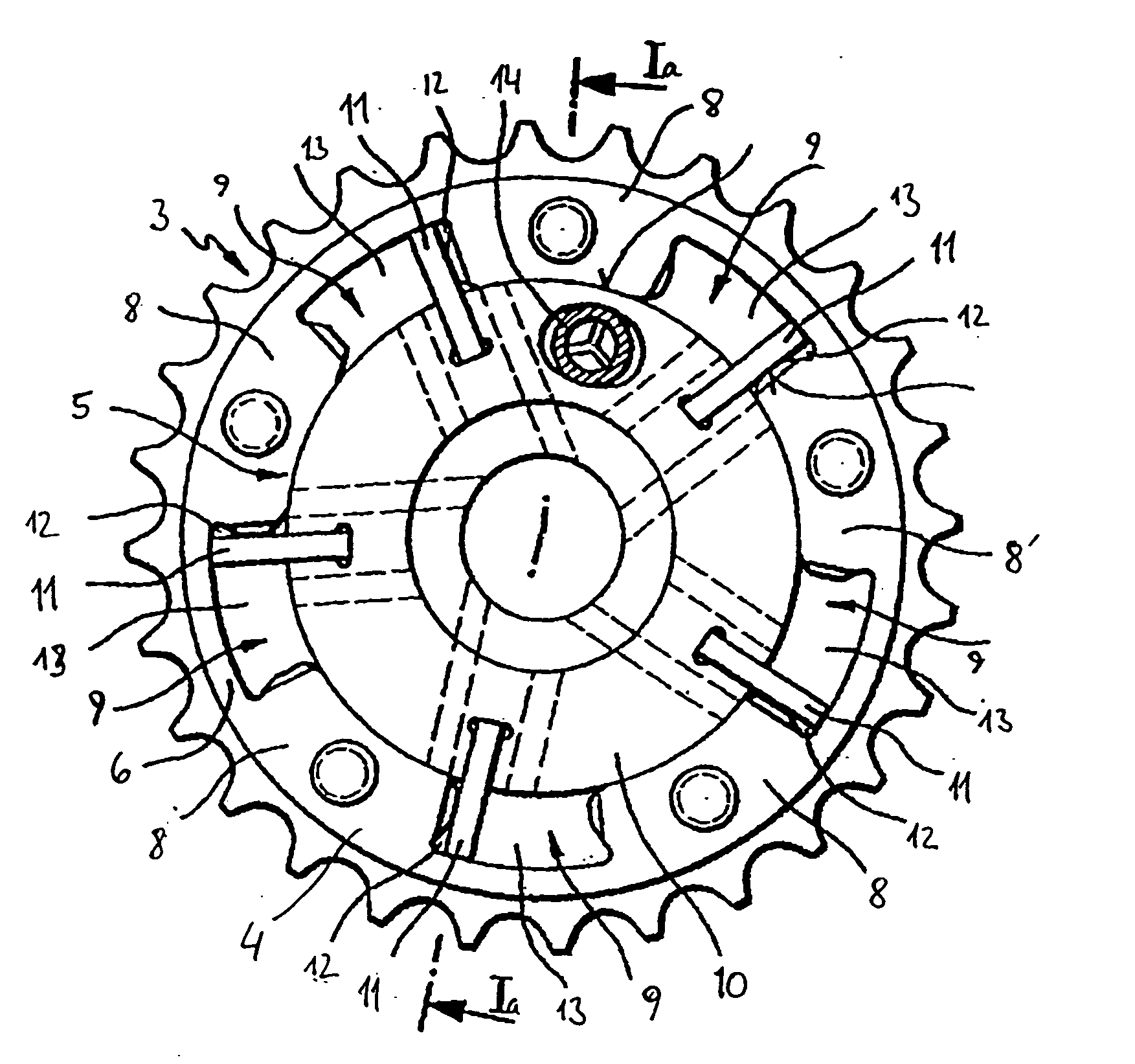
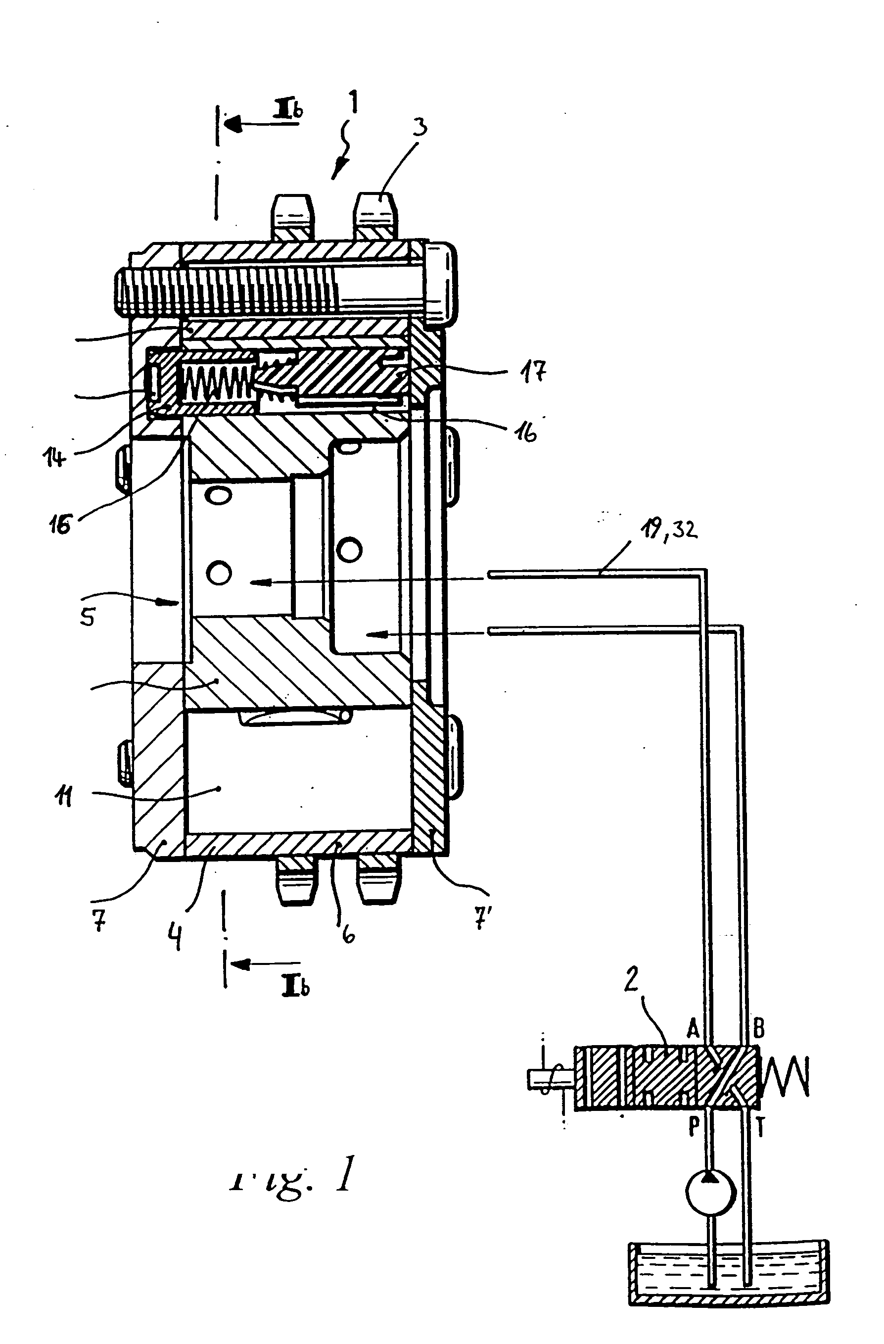
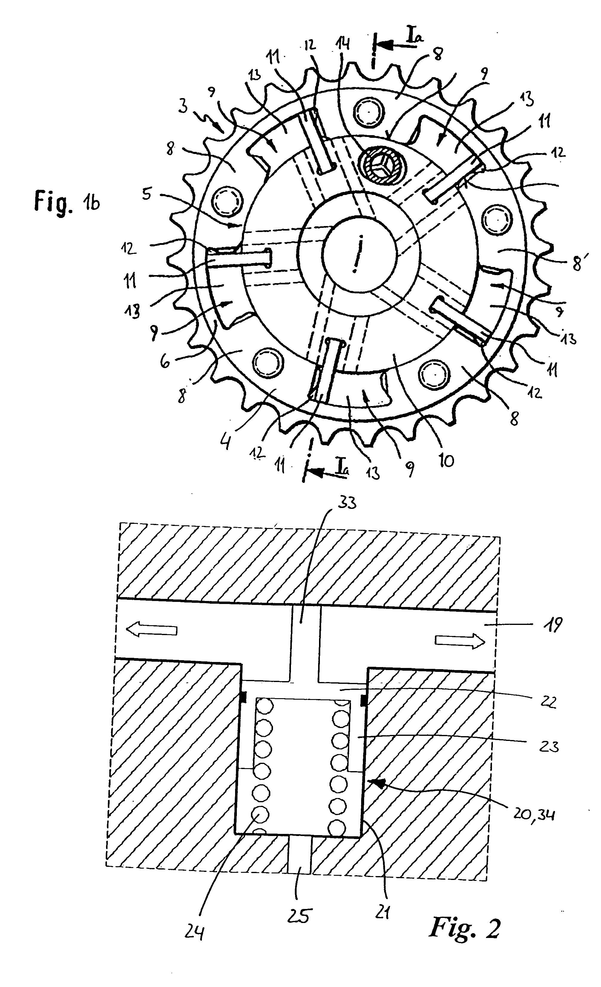
[0033] A device 1 for adjusting the rotation angle between a crankshaft (not represented) and a camshaft (likewise not represented) is shown in FIGS. 1a and 1b. This device 1 is attached as a rotation piston adjusting device to the drive-side end of the camshaft mounted in the cylinder head (not represented) of an internal combustion engine and is configured, in principle, as a hydraulic actuating drive, which is controlled dependent on various operating parameters of the internal combustion engine by a hydraulic valve 2, via hydraulic fluid lines 19 of a hydraulic fluid system 32.
[0034] The device 1 essentially comprises a stator 4, which is drive-connected to the crankshaft by a drive wheel 3, and a rotor 5, which is connected in a rotationally secure manner to the camshaft. The rotor 5 is pivotably mounted in and is in power-transmission connection with the drive wheel 3. The drive wheel 3 in this case has a cavity, which is formed by a hollow-cylindrical peripheral wall 6 and t...
PUM
 Abstract
Description
Claims
Application Information