Pressure control valve device

Active Publication Date: 2013-05-30
ZF FRIEDRICHSHAFEN AG
View PDF14 Cites 10 Cited by
  • Summary
  • Abstract
  • Description
  • Claims
  • Application Information

AI Technical Summary

Benefits of technology

The present invention aims to provide a valve device that is less sensitive to changes in pressure.

Problems solved by technology

Especially in the low-load range of a powershift automatic transmission, for example during coasting downshifts, as described earlier the system-inherent inflow pressure dependence of pressure-control valves is perceived as particularly annoying.
This is particularly the case if in such load conditions inflow pressure fluctuations and in particular inflow pressure drops occur so that deviations from nominal pressure are produced, which when amplified by clutch valve transmission ratios give rise to unacceptable shifting behavior.

Method used


Image

  • Pressure control valve device
  • Pressure control valve device
  • Pressure control valve device

Examples


Embodiment Construction

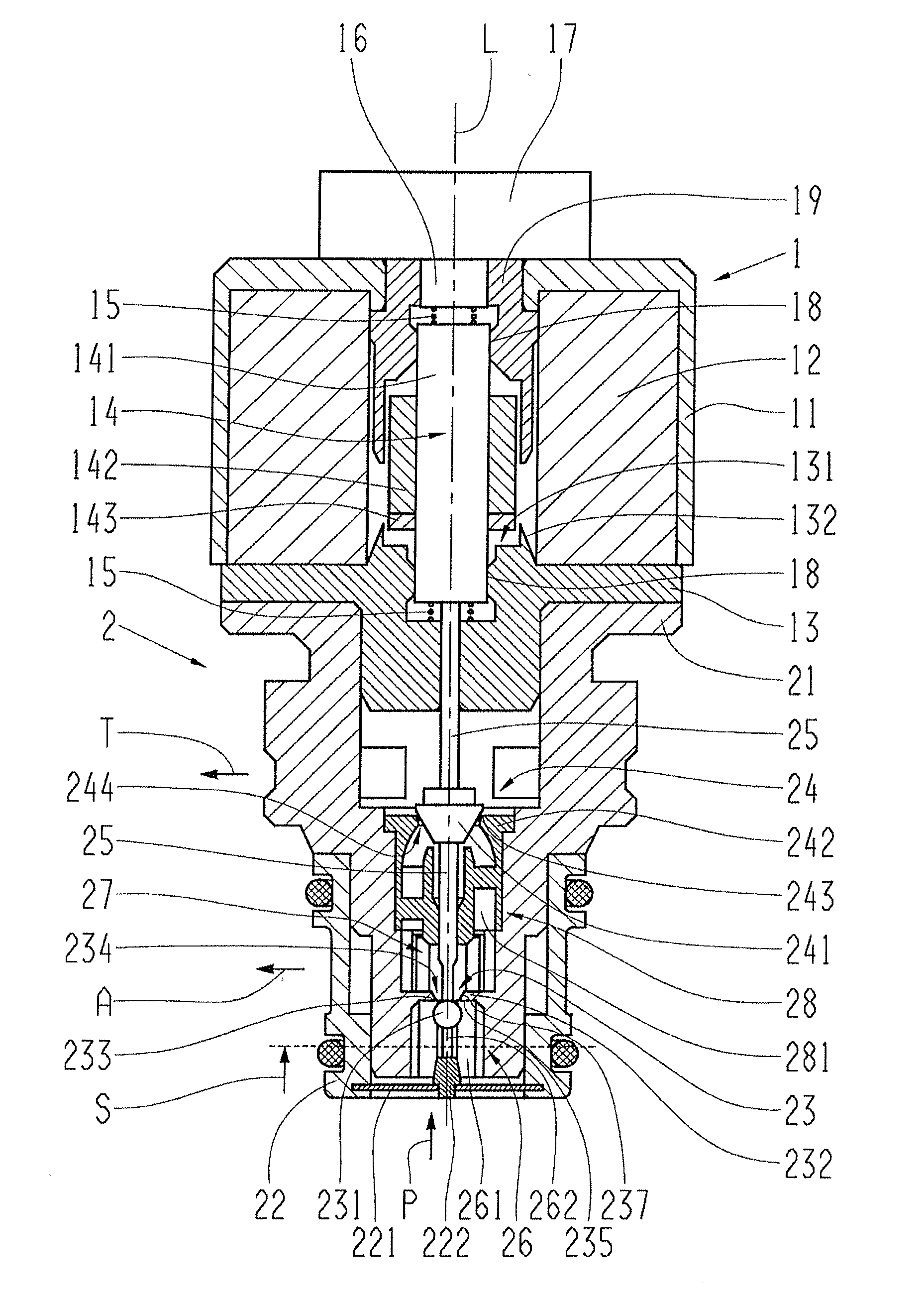
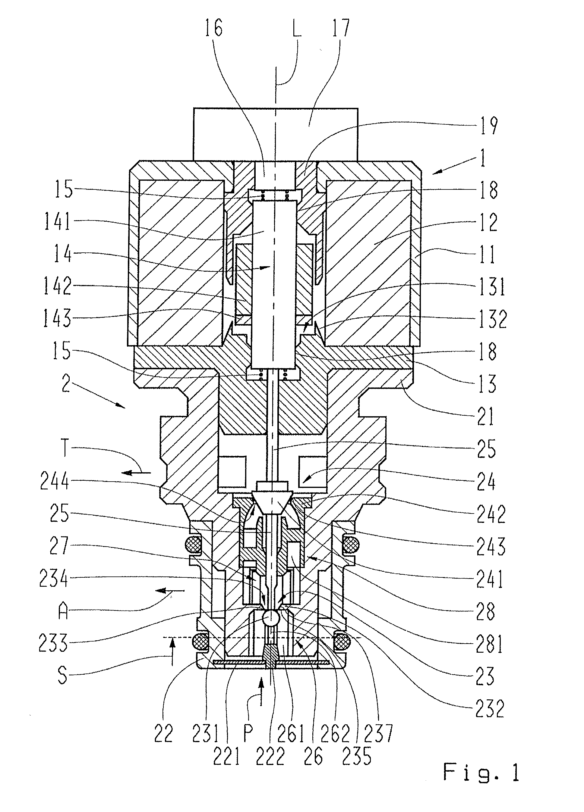
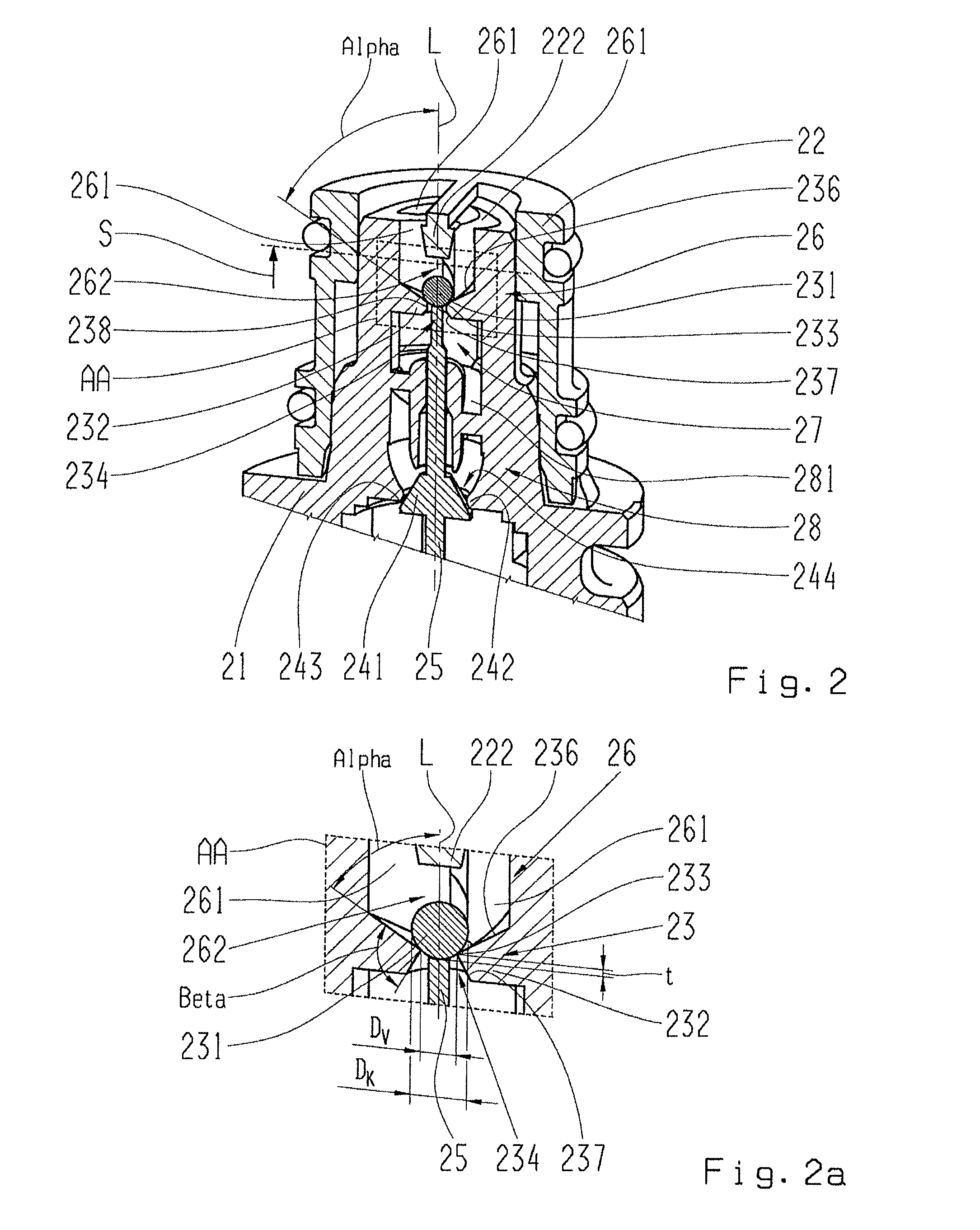
[0045]In FIGS. 1 to 4 the same components, or at least components having the same function, are in each case provided with the same indexes.

[0046]FIG. 1 shows a longitudinal section through a pressure-control valve device made as a proportional pressure-control valve. The pressure-control valve device comprises essentially of an electromagnet portion 1, i.e. an actuator, and a valve portion 2, whose housings 11, 21 are connected fixed to one another. The electromagnet position 1 comprises an electromagnet consisting at least of an electric solenoid 12 arranged in the housing 11, a magnetic yoke 13 positionally fixed relative to the solenoid 12 and an armature 14 that can move relative to the solenoid 12 and the magnetic yoke 13. In the case illustrated the armature 14 is made in three parts and comprises an armature rod 141, an armature body 142 and an anti-sticking disk 143 made of a nonmagnetic material such as aluminum. However, other armature designs or types can be used equival...


PUM


Abstract

A pressure-control valve device for a fluid, having at least one inlet area and first and second outlet areas that can be flow-connected to one another by two seat valves coupled to one another, in which a fluid flow from the inlet area to the first and second outlet areas can be adjusted by the first seat valve and a fluid flow between the first and second outlet areas can be adjusted by the second seat valve. The first seat valve is designed as a valve aperture with a valve opening and a valve control edge and with a ball-shaped closing element that co-operates with the valve control edge. The valve opening and the ball-shaped closing element are designed such that the ratio of the diameter of the valve opening to the diameter of the ball-shaped closing element is equal to at least 0.75.

Description

[0001]This application claims priority from German patent application serial no. 10 2011 087 264.7 filed Nov. 29, 2011.FIELD OF THE INVENTION[0002]The invention relates to a pressure-control valve device for a fluid.BACKGROUND OF THE INVENTION[0003]In multi-stage motor vehicle automatic transmissions known from current practice shifting elements designed as wet-operating clutches or brakes are used between a transmission input shaft and a transmission output shaft of the automatic transmission for engaging various gear steps. For this, depending on the gear step desired, opening or closing of the shifting elements takes place. The pressure force required for this is usually applied for each shifting element by a hydraulically actuated clutch piston, which is supplied with hydraulic fluid by way of shifting element valves also known as pressure-reducing valves. These pressure-reducing valves are either themselves designed as proportional pressure-control valves or they are actuated b...

Claims


Application Information

Patent Timeline
IPC IPC(8): F16K17/00
CPCG05D16/2013F16K17/00G05D16/2024Y10T137/87217
Inventor MAYR, KARLHEINZMOOSMANN, MARKUSHAMMA, FRANKREMMLINGER, HUBERT
Owner ZF FRIEDRICHSHAFEN AG
Why Eureka
Try Eureka