Fluid supply apparatus

a technology of fluid supply apparatus and pump, which is applied in the direction of positive displacement liquid engine, pump, machine/engine, etc., can solve the problems of device size and resource saving

Inactive Publication Date: 2014-05-08
SEIKO EPSON CORP
View PDF9 Cites 16 Cited by
  • Summary
  • Abstract
  • Description
  • Claims
  • Application Information

AI Technical Summary

Benefits of technology

[0007]An advantage of some aspects of the invention is to solve at least a part of the problems described above, and the invention can be implemented as the following aspects.

Problems solved by technology

For example, in the case where the technique is applied to a fluid supply apparatus which feeds a fluid to a water jet knife as a medical apparatus, a problem is pointed out that a pulsating flow is generated in the fluid ejected from the water jet knife, which is undesirable to the operation of the water jet knife.
Also, various other issues are pointed such as reduction in size of the device, reduction in cost, resource saving, easier manufacturing, and improvement in user-friendliness.
Such problems are equally seen in devices for supplying a fluid not only to a water jet knife but also to other medical apparatuses.

Method used


Image

  • Fluid supply apparatus
  • Fluid supply apparatus
  • Fluid supply apparatus

Examples


first embodiment

A. First Embodiment

A1. System Configuration

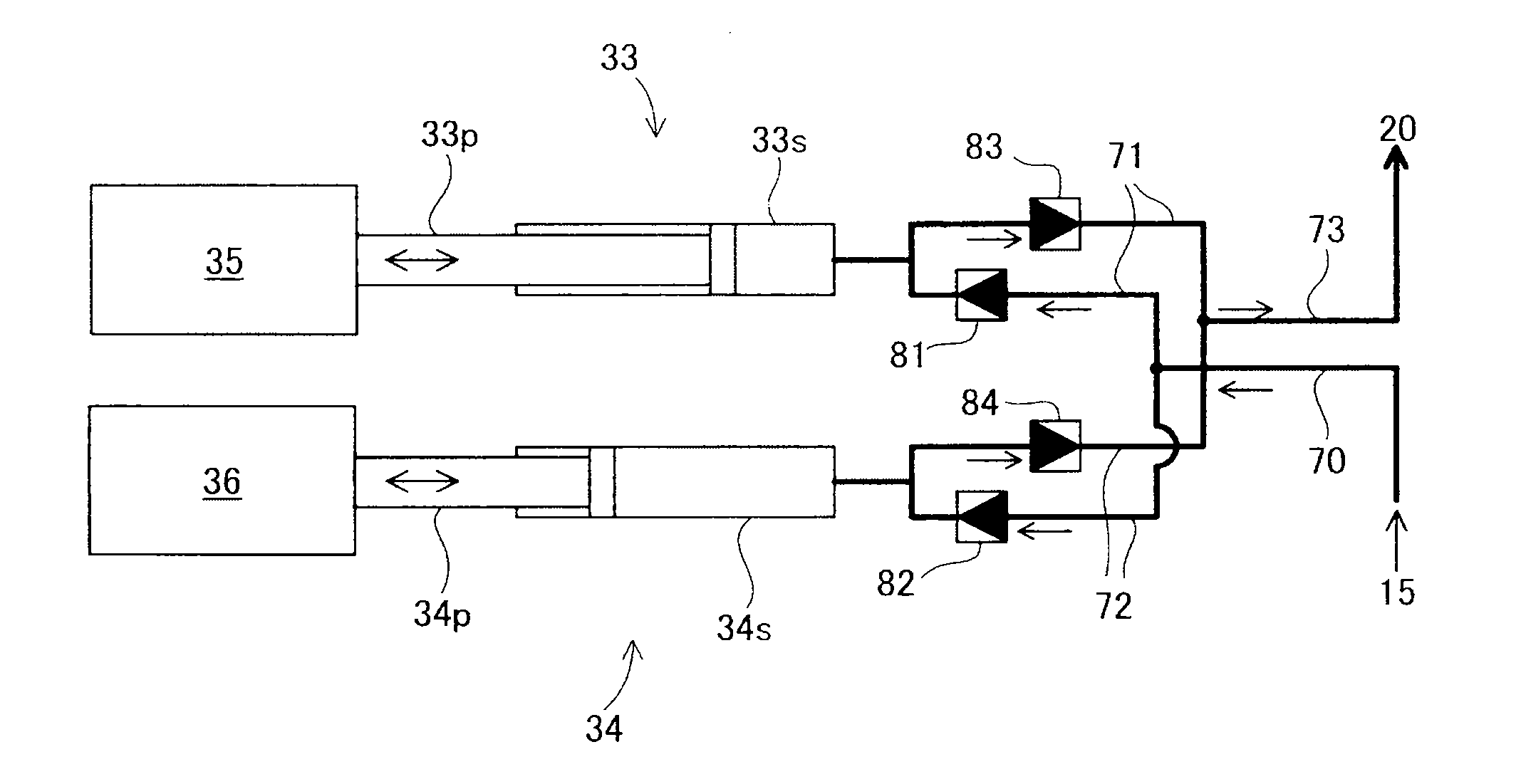
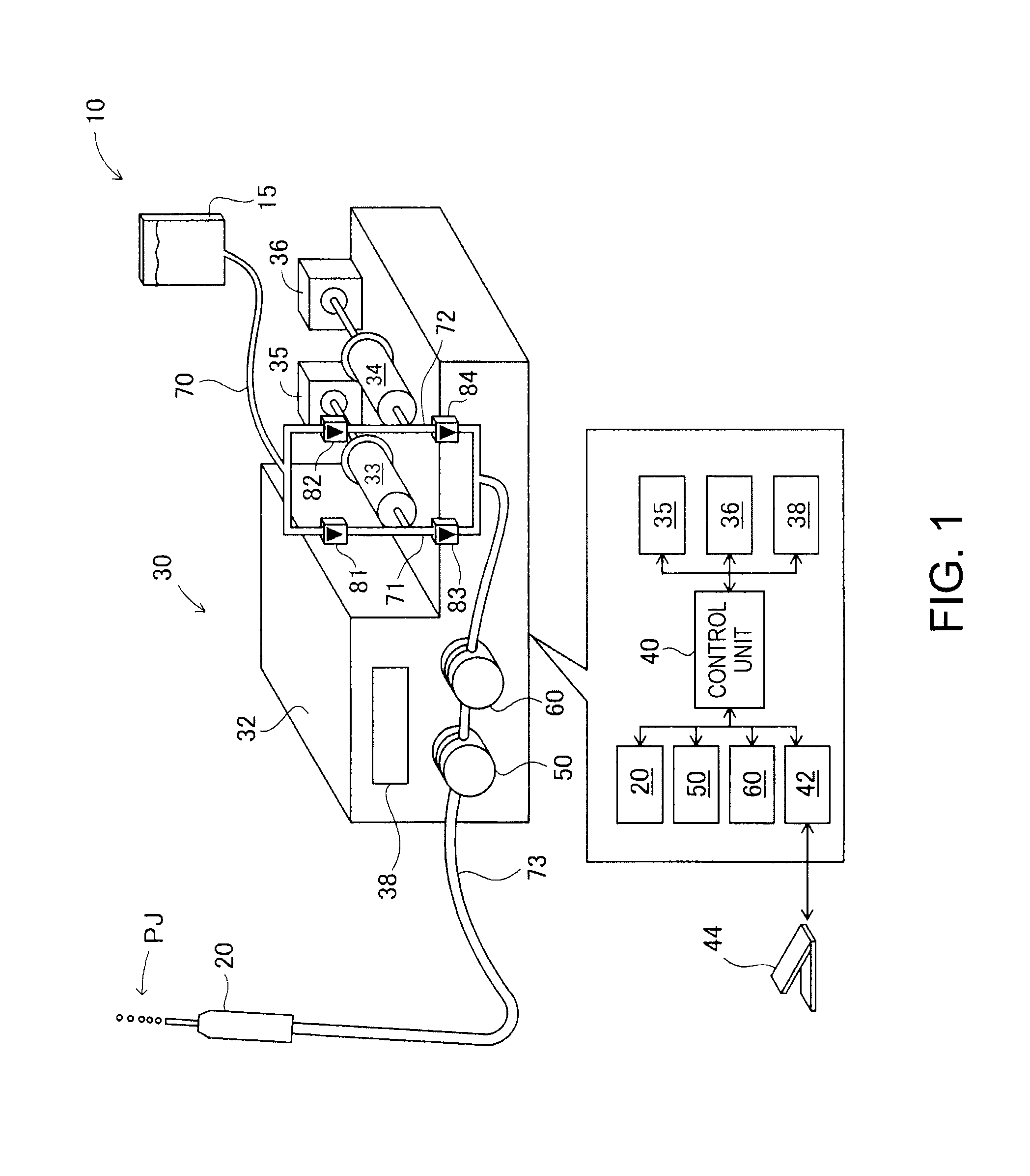
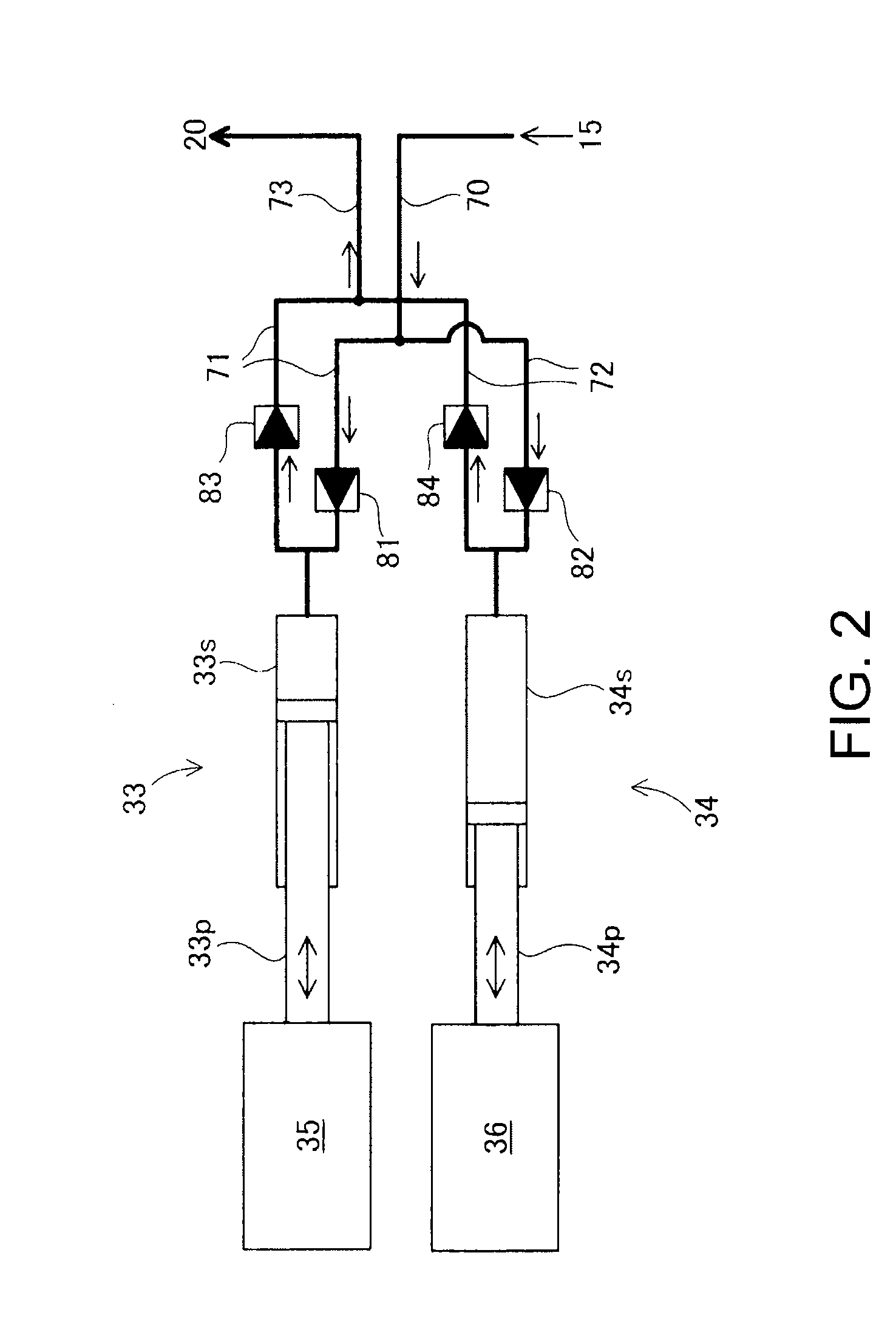
[0035]FIG. 1 is an explanatory view illustrating a water jet knife system 10 using a fluid supply apparatus as a first embodiment of the invention. A water jet knife is a kind of surgical knife and ejects a fluid at a high pressure to perform incision and excision with the discharge pressure. In this embodiment, sterilized water is employed as a fluid to be ejected.

[0036]The water jet knife system 10 has a water jet knife 20, a fluid supply apparatus 30 which supplies water to the water jet knife 20, and a fluid storage unit 15 which stores water to be supplied to the water jet knife 20. The water jet knife 20 has, inside itself, a mechanism which generates a pulse water flow using a piezoelectric element as a power source. In the water jet knife 20, the piezoelectric element is driven at a predetermined frequency to eject water supplied from the fluid supply apparatus 30 to outside as a pulsed high-pressure jet water flow (pulse jet PJ). T...

second embodiment

B. Second Embodiment

[0067]A second embodiment of the invention will be described. FIG. 9 is an explanatory view showing a water jet knife system 10a as a second embodiment. This embodiment is different from the first embodiment in that the fluid supply apparatus 30 has a pressure fluctuation detecting unit 64 inside the flow passage deforming mechanism 50, instead of the pressure fluctuation detecting unit 60. Thus, as illustrated, the control unit 40 is connected to the pressure fluctuation detecting unit 64 and controls the operation thereof.

[0068]FIG. 10 is a vertical sectional view of the flow passage deforming mechanism 50 including the pressure fluctuation detecting unit 64. In this embodiment, the pressure fluctuation detecting unit 64 is formed as a load cell which measures a load. As illustrated, the pressure fluctuation detecting unit 64 faces the pressing portion 54 via the flow passage 73 and is installed in such a way that the pressure fluctuation detecting unit 64 and ...

modification 1

C1. Modification 1

[0075]In the above embodiments, the pressure fluctuation detecting unit 60 and the pressure fluctuation detecting unit 64 are employed as a pressure fluctuation detecting unit for detecting fluctuation in the internal pressure in the flow passage. However, various other configurations can be employed without being limited to the above. FIG. 13 is an explanatory view showing a configuration in which the fluid supply apparatus 30 has a strain gauge 65 as a pressure fluctuation detecting unit, as an example of Modification 1. As illustrated, the strain gauge 65 is pasted and thus installed on the flow passage 73. The amount of strain of the flow passage 73 detected by the strain gauge 65 is converted to the amount of fluctuation in internal pressure by the control unit 40.

[0076]Specifically, the correlation between the internal pressure in the flow passage 73 as an independent component and the amount of strain measured by the strain gauge 65 is measured in advance, a...


PUM


Abstract

A fluid supply apparatus which supplies a fluid to a medical apparatus includes: a pump mechanism including a first pump capable of carrying out a intake operation of a fluid and a feeding operation of the fluid, and a second pump capable of alternately carrying out a intake operation of the fluid and a feeding operation of the fluid; a flow passage which includes an elastic member and which communicates with the pumps and supplies the fluid to the medical apparatus; a pressure fluctuation detecting unit capable of detecting fluctuation in internal pressure in the flow passage; and a flow passage deforming unit which deforms the flow passage according to the fluctuation in the internal pressure.

Description

[0001]This application claims priority to Japanese Patent Application No. 2012-244984 filed on Nov. 7, 2012. The entire disclosure of the Japanese Patent Application No. 2012-244984 is hereby incorporated herein by reference.BACKGROUND[0002]1. Technical Field[0003]The present invention relates to a technique for supplying a fluid to a medical apparatus.[0004]2. Related Art[0005]According to a related art, for example, a technique disclosed in JP-A-9-264261 is known as a technique for stably feeding a fluid. JP-A-9-264261 discloses a technique in which when one of two plunger pumps is carrying out an discharge process at a predetermined discharge pressure, the other stands by in the state of pre-pressurizing the fluid, and when the discharge pressure of the one plunger pump begins to fall, the other starts a pressurization and discharge process of the fluid and raises the pressure to a target discharge pressure within a short time, thus carrying out discharge continuously.[0006]Howev...

Claims


Application Information

Patent Timeline
Patent Type & Authority Applications(United States)
IPC IPC(8): F04B11/00F04B49/22A61M5/172F04B7/00
CPCF04B11/005F04B7/0076F04B49/225A61M5/172A61M5/16854F04B23/06
Inventor UCHIDA, KAZUAKISETO, TAKESHIMATSUZAKI, TAKAHIROHIRABAYASHI, ATSUYA
Owner SEIKO EPSON CORP
Why Eureka
Try Eureka