Method and device for cleaning filters for dust-laden waste gases

Inactive Publication Date: 2007-11-27
SCHEUCH GMBH
View PDF23 Cites 16 Cited by
  • Summary
  • Abstract
  • Description
  • Claims
  • Application Information

AI Technical Summary

Benefits of technology

[0027]If, in accordance with a further characteristic feature of the invention, the at least one waste-gas supply duct is arranged below the lower end of the filter elements of the filter module

Problems solved by technology

Here, the complete separation of the filter modules to be dedusted from the crude-gas flow is not sou

Method used


Image

  • Method and device for cleaning filters for dust-laden waste gases
  • Method and device for cleaning filters for dust-laden waste gases
  • Method and device for cleaning filters for dust-laden waste gases

Examples


Embodiment Construction

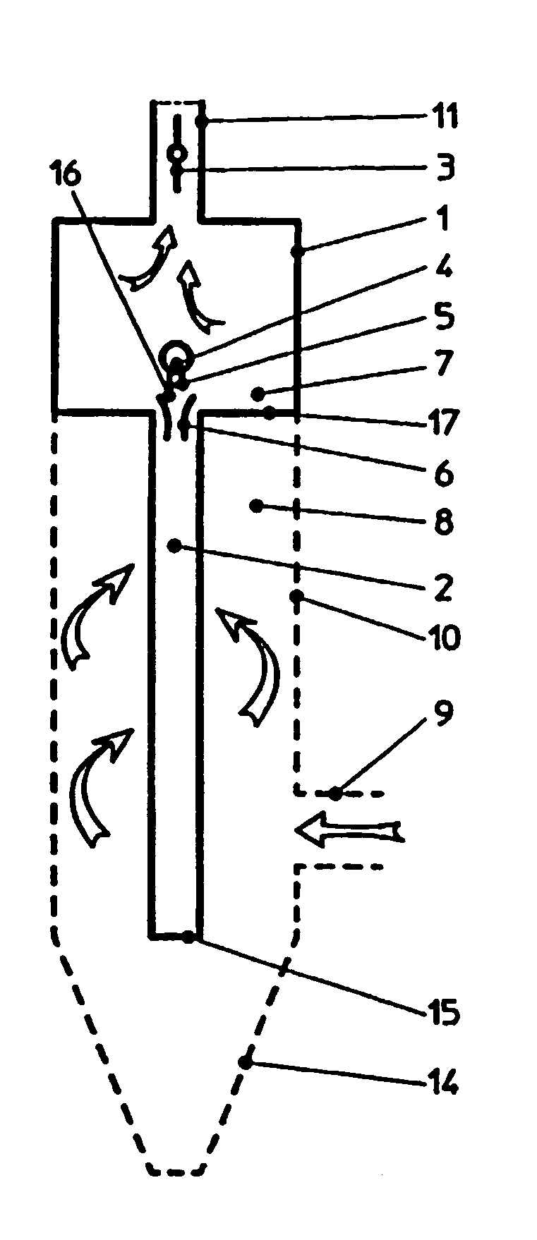
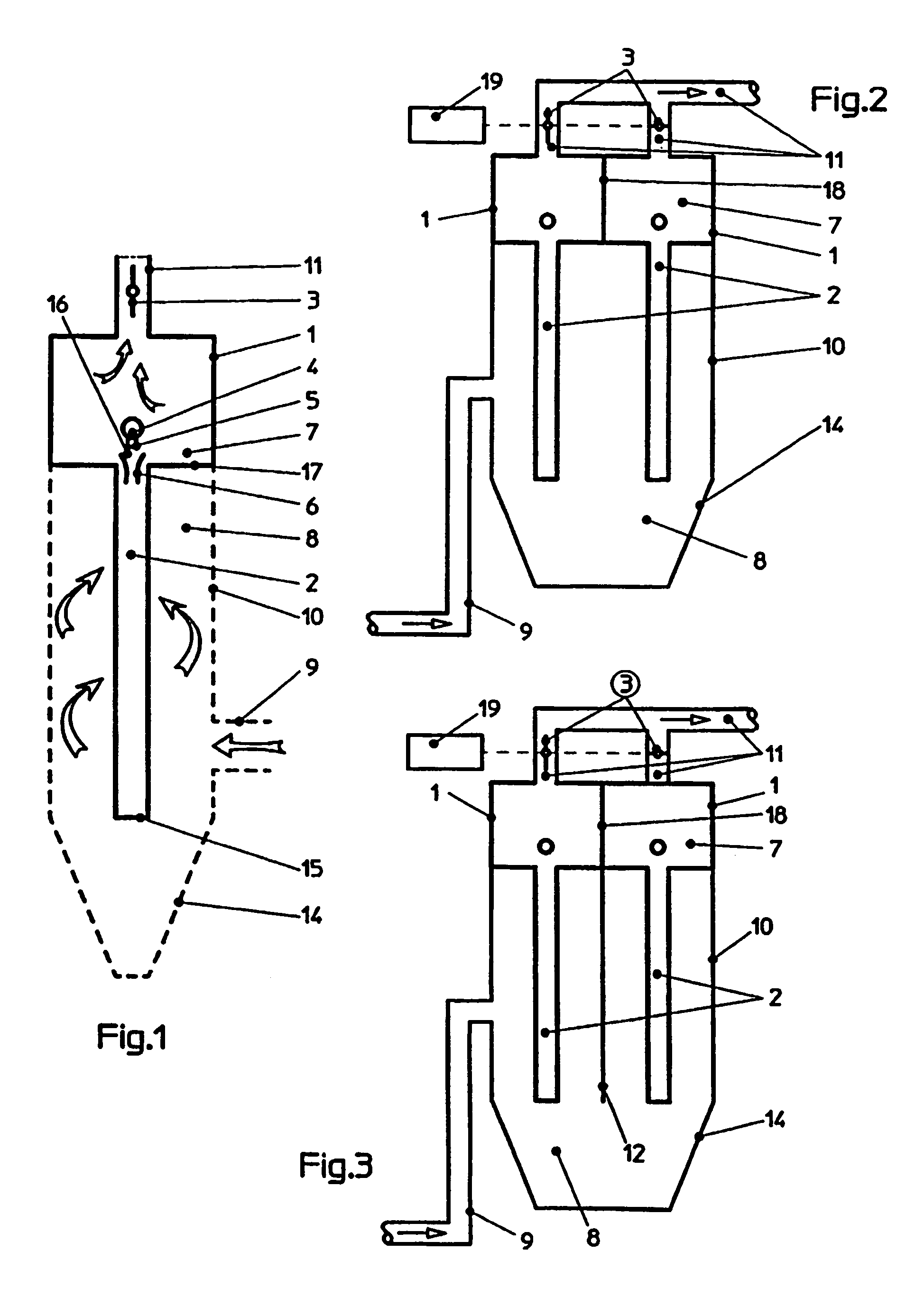
[0034]FIG. 1 shows a filter module 1, in which at least one filter element 2 comprised of a filter hose is arranged. As a rule, a row of filter elements 2, or even several rows of filter elements 2, are arranged in a filter module 1. Each one of said filter elements 2 is vertically arranged and comprises a closed, lower end 15 as well as an open, upper end 16. Each one of said filter elements 2 is suspended in an opening of a plate 17 that separates the crude-gas space 8 from the clean-gas space 7, the crude-gas flow introduced into the filter housing 1 through a supply duct 9 flowing through each of said filter elements from outside towards inside. The impurities contained in the crude-gas flow remain adhered to the outer walls of the filter elements 2, forming a filter cake that will grow over time. The cleaned crude gas reaches the clean-gas space 7 via the upper, open end 16 of the filter element 2, and from there flows to consecutively provided plant parts, or into the atmosphe...


PUM

PropertyMeasurementUnit
Lengthaaaaaaaaaa
Timeaaaaaaaaaa
Pressureaaaaaaaaaa

Abstract

The invention relates to a method for cleaning filters for dust-laden waste gases, including several filter elements (2) which are arranged vertically in a filter housing (1) and which have an upper open end (16) and a lower closed end (15) with at least one feed line (9) for the dust-laden waste gases and at least one discharge line (11) for the cleaned waste gases, in addition to a device for injecting surges of compressed air into the open end (16) of the filter elements (2). In order to reduce pressure fluctuations in the filter and to provide efficient cleaning with pulsations of compressed air in the low pressure range i.e. from approximately 0.8 to 3 bars, the filter is divided into several filter modules (1) respectively including at least one filter element (2). At least two filter modules (1) are arranged in a filter housing (10) or a filter chamber. The filter modules (1) are cleaned alternately and each filter module (1) is associated with a discharge line (11) with a shut-off element (3) for the clean gas. A control device (19) is provided for the shut-off elements (3), whereby when the filter modules (1) which are to be cleaned are changed, the shut-off element (3) of the cleaned filter modules (1) is open and the shut off element (3) is closed in a diametrically opposed manner for the filter module (1) to be cleaned. As a result, any pressure fluctuations in the filter are minimised.

Description

BACKGROUND OF THE INVENTION[0001]The invention relates to a method and device for dedusting filters for dust-laden waste gases, including several vertically arranged filter elements each having an upper, open end and a lower, closed end, wherein the waste gases flow through the filter elements from outside and the cleaned waste gases are discharged through the open ends of the same, and wherein for dedusting compressed-air blasts are blown into the open ends of the filter elements to be dedusted.[0002]Filters for dust-laden waste gases are used where impurities such as as chips, shreds, fibers or dusts are to be separated from a conveying air and disposed of or recycled. Examples of industrial branches where lots of dust occur include the wood-processing industry, fiber industry, paper industry or petroleum industry. Impurities are, for instance, sucked off the location of a processing machine, and the polluted waste gases, which are referred to as crude gases, are supplied to the f...

Claims


Application Information

Patent Timeline
IPC IPC(8): B01D50/00B01D46/42B01D46/00B01D46/04
CPCB01D46/0013B01D46/002B01D46/04B01D46/0068B01D46/0058B01D46/90B01D46/58B01D46/71
Inventor SCHEUCH, ALOIS
Owner SCHEUCH GMBH
Why Eureka
Try Eureka