
Laser light source device and parking indicator light system including same

a technology of parking indicator light and laser light source device, which is applied in the direction of lighting and heating equipment, instruments, transportation and packaging, etc., can solve the problems of minor accidents between vehicles or between vehicles or between vehicles and facilities, significant installation cost, and risk of generating accidents, so as to facilitate traveling and limit the effect of road width

Active Publication Date: 2020-07-07
SEONGWON TPS INC
View PDF18 Cites 0 Cited by
  • Summary
  • Abstract
  • Description
  • Claims
  • Application Information

AI Technical Summary

Benefits of technology

The present invention is a parking indicator light system that helps drivers easily recognize the directions they need to travel and park in a limited road width, narrow view, and dim illumination. The system uses a laser beam to create an indicating line, which minimizes installation and management costs. Overall, this invention improves parking efficiency and driver safety in underground lots.

Problems solved by technology

In general, minor accidents between vehicles or a vehicle and a facility such as a wall frequently occur within an underground parking lot having a limited road width, narrow view, and dim illumination.
In particular, although a separate lighting is installed within an underground parking lot, a driver may hardly recognize circumstances around a road due to low brightness and narrow view and thereby, there is always a risk of generating accidents.
However, various numbers of the systems need to be installed densely at regular intervals on each part of a road for one area so that the installation cost is significantly high and it is hard to manage the system.
Since the laser beam is a point light source traveling straight, a projected area is limited.

Method used


Image

  • Laser light source device and parking indicator light system including same
  • Laser light source device and parking indicator light system including same
  • Laser light source device and parking indicator light system including same

Examples


Embodiment Construction

[0030]Before the description, it will be understood that when a part “comprises” or “includes” an element, the part may further include another element rather than excluding another element, unless the contrary description is not specifically mentioned. Also, the term “unit” used in the description denotes a unit that performs at least one function or operation and may be embodied as hardware, software, or a combination of hardware and software.

[0031]In addition, the term “embodiment” in the description denotes an example, an instance, or an illustration, however, an object of the present invention is not limited to the embodiment. It will be further understood that the terms “comprises,”“includes,” and / or “has,” when used in claims, are open transition words which do not exclude addition or other elements and are comprehensively used as in a similar manner as in the term “comprising”.

[0032]Various techniques described in the description may be embodied with hardware or software or,...


PUM

PropertyMeasurementUnit
angleaaaaaaaaaa
angleaaaaaaaaaa
lengthaaaaaaaaaa

Abstract

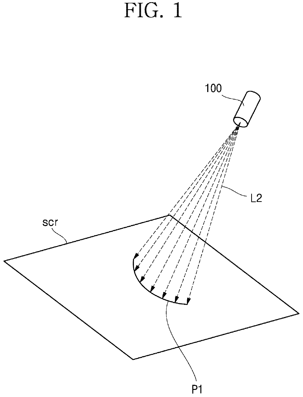
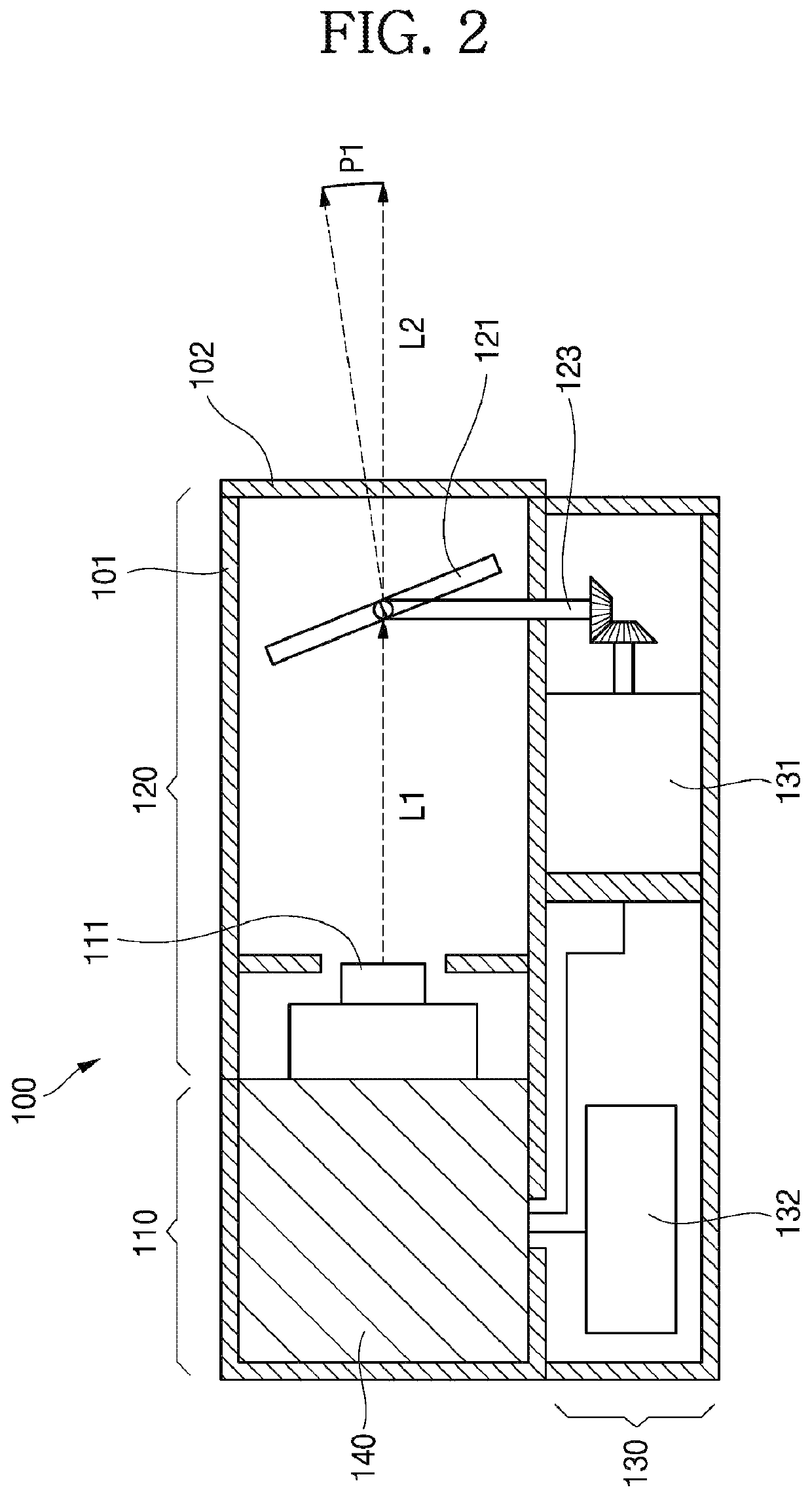
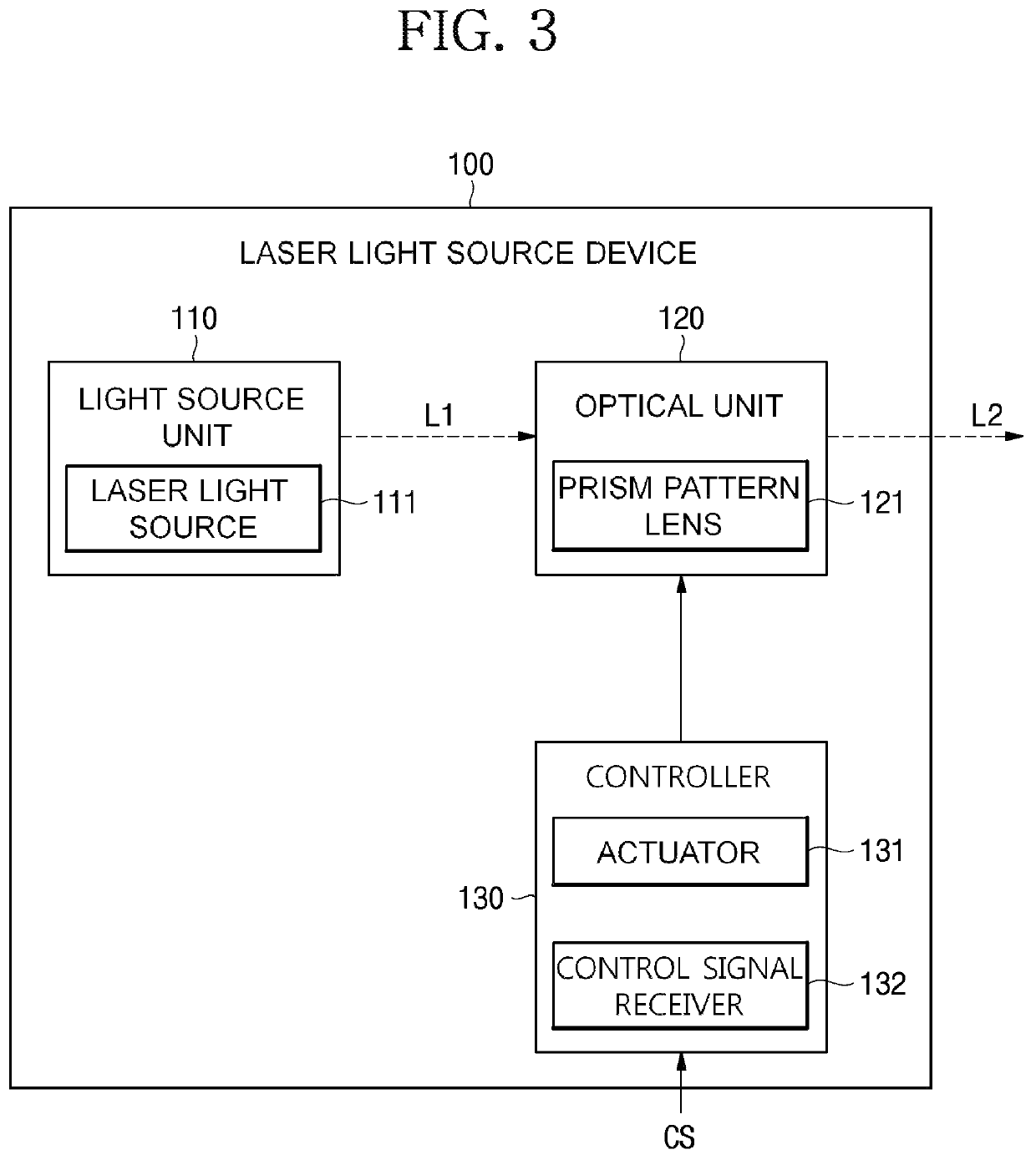
A laser light source device of the present invention is disclosed. More specifically, the present invention relates to a laser light source device for emitting a deflected light so as to form a specific shape by outputting a laser beam through a point light source, and a parking indicator light system including the same. According to an embodiment of the present invention, an indicating line according to a road shape is projected and displayed on a road surface within an underground parking lot such that a driver may easily recognize traveling and parking directions of a vehicle on a road with a limited road width, narrow view, and dim illumination.

Description

BACKGROUND OF THE INVENTION1. Field of the Invention[0001]The present invention relates to a laser light source device, and more particularly, to a laser light source device for emitting deflected light so as to form a specific shape by outputting a laser beam through a point light source, and a parking indicator light system including the same.2. Description of the Related Art[0002]In general, minor accidents between vehicles or a vehicle and a facility such as a wall frequently occur within an underground parking lot having a limited road width, narrow view, and dim illumination. In particular, although a separate lighting is installed within an underground parking lot, a driver may hardly recognize circumstances around a road due to low brightness and narrow view and thereby, there is always a risk of generating accidents.[0003]In order to minimize generation of such accidents and to facilitate safe traveling of vehicles, various types of vehicle guidance system and indicator lig...

Claims


Application Information

Patent Timeline
Patent Type & Authority Patents(United States)
IPC IPC(8): G02B26/08F21S41/16G08G1/14
CPCF21S41/16G02B26/0883G08G1/14G02B5/045G02B26/108G02B19/0014G02B19/0052G02B27/20G08G1/142G08G1/149
Inventor MIN, SA HYUN
Owner SEONGWON TPS INC
Learn More