

Stator and electric pump
- Summary
- Abstract
- Description
- Claims
- Application Information
AI Technical Summary
Benefits of technology
Problems solved by technology
Method used
Image

Examples
embodiment
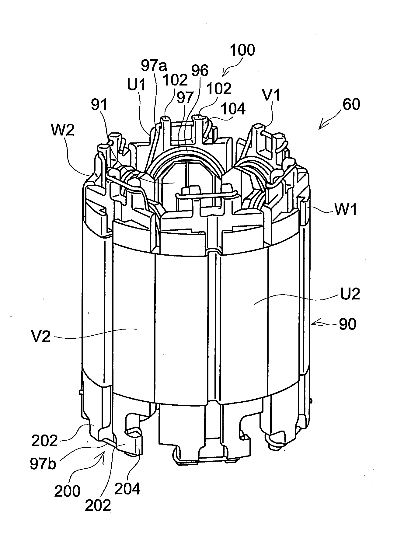
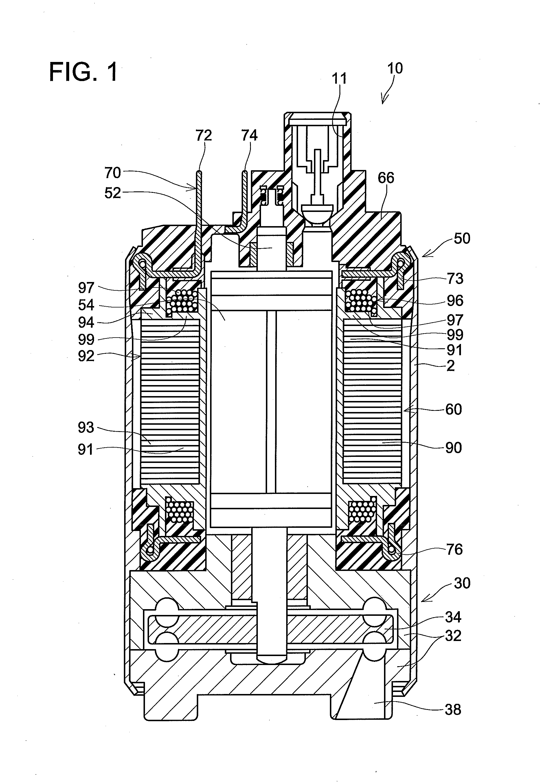
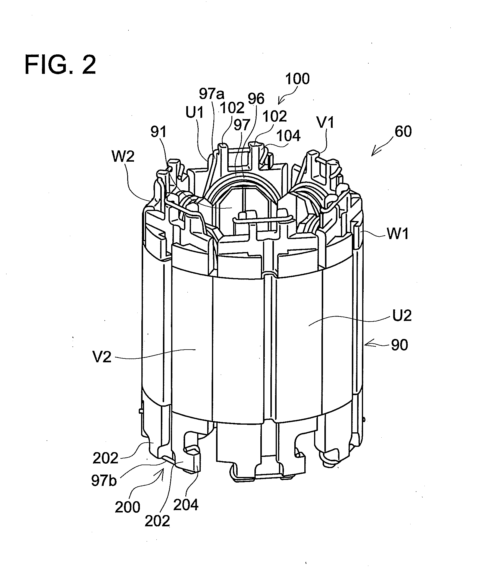
[0029]As shown in FIG. 1, a stator 60 according to the present embodiment is used in a fuel pump 10. The fuel pump 10 is disposed in a fuel tank (not shown). The fuel pump 10 supplies fuel (such as gasoline) to an engine (not shown) of a vehicle such as an automobile. The fuel pump 10 comprises a motor portion 50 and a pump portion 30. The motor portion 50 and the pump portion 30 are disposed in a housing 2. The housing 2 has a tubular shape with both ends opened.
[0030]The pump portion 30 comprises a casing 32 and an impeller 34. The casing 32 closes an opening of a lower edge of the housing 2. At the lower edge of the casing 32, an intake port 38 is provided. At an upper edge of the casing 32, a through-hole (not shown) for communicating between an inside of the casing 32 and the motor portion 50 is provided. The impeller 34 is provided within the casing 32.
[0031]The motor portion 50 is positioned above the pump portion 30. The motor portion 50 is a brushless motor. The motor porti...
PUM
 Abstract
Description
Claims
Application Information