Humeral implant for a shoulder prosthesis

a technology of humeral implants and shoulder prostheses, which is applied in the field of orthopaedic implants, can solve the problems of not being able to determine well in advance whether a traditional or reverse shoulder is appropriate, significant resection of cancellous bone, and fracture of the humerus metaphyseal area, etc., and achieve the effect of optimal distribution

Active Publication Date: 2016-02-25
LIMA CORPORATE SPA
View PDF45 Cites 53 Cited by
  • Summary
  • Abstract
  • Description
  • Claims
  • Application Information

AI Technical Summary

Benefits of technology

[0015]The aim of the present invention is to provide a novel humeral implant overcoming the above mentioned drawbacks. In particular, it is an object of the present invention to provide an humeral implant that achieves an anatomical optimal distribution of loads and that do not need removal from the patient in case of conversion from the anatomical configuration to the reverse.

Problems solved by technology

It is not always practical to determine well in advance of the procedure whether a reverse or traditional shoulder prosthesis should be used.
One disadvantage of this anchoring stem is that it requires, on the basis of the dimensions of the head of said stem, a significant resection of cancellous bone.
In addition, the positioning of the stem leads to modify the original positioning of the humeral head and of its center of rotation, which could lead to a fracture of the humerus metaphyseal area.
In general, the problems related to humeral component with a stems are the following: the offset between the centre of rotation of the head and the axis of the diaphysis, implantation surgery is more difficult and the required time is longer compared to stemless procedures, postoperative complications are dominated by fractures, the removal of the stem in case of revision surgery is necessary.

Method used


Image

  • Humeral implant for a shoulder prosthesis
  • Humeral implant for a shoulder prosthesis
  • Humeral implant for a shoulder prosthesis

Examples


Embodiment Construction

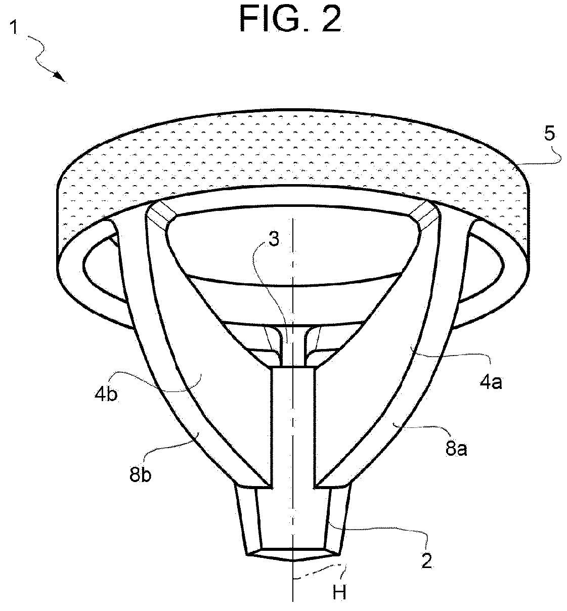
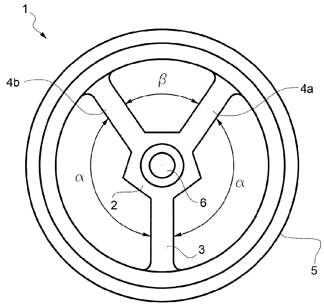
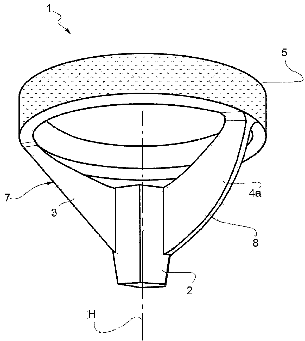
[0028]FIGS. 1-3 indicate with numeral 1 as a whole a support element for an humeral implant according to the invention.

[0029]The support element 1 comprises a central body 2 extending along an axis H. The central body 2 has three arms 3, 4a and 4b extending outwardly from the central body 2 and transversely positioned with respect to the axis H. The number of the arms may vary from 3 to 5.

[0030]The three arms 3, 4a and 4b bear a ring element 5 at their ends opposite to said central body 2. The ring element 5—according to a first embodiment of the invention—comprises a cylindrical tubular body coaxial to axis H. The tubular body is one piece with arms 3, 4a and 4b.

[0031]According to a different embodiment (FIG. 4), tubular body comprises a first cylindrical portion 5a coaxial to axis H and a second integral cylindrical portion 5b coaxial to a different axis H1 forming an angle γ with axis H. Arms 3, 4a and 4b and are spaced one with respect to the other along the axis H so that at l...


PUM


Abstract

The invention discloses a support element for humeral implant comprising a central body extending along an axis and at least three arms extending outwardly from the central body, the arms being transversal to said axis and bearing a ring element at their ends opposite to said central body, wherein at least a first and a second pair of arms form different angles.

Description

TECHNICAL FIELD[0001]The present invention relates to orthopedic implants, in particular shoulder prostheses.BACKGROUND ART[0002]A natural shoulder joint may undergo degenerative changes caused by a variety of reasons. When these degenerative changes become so far advanced and irreversible, it may ultimately become necessary to replace a natural shoulder joint with a prosthetic shoulder joint. In the traditional implantation of a shoulder joint prosthesis, the natural head portion of the humerus is resected and a cavity is created in the intramedullary canal of the host humerus for accepting a humeral component. The humeral component generally includes a stem, and a head portion, which is used to replace the natural head of the humerus. Once the humeral component has been implanted, the glenoid cavity positioned at the scapula may also be resected and shaped to accept a glenoid component. The glenoid component generally includes an articulating surface or cup which is engaged by the...

Claims


Application Information

Patent Timeline
Patent Type & Authority Applications(United States)
IPC IPC(8): A61F2/40
CPCA61F2/4014A61F2/4003A61F2002/30113A61F2002/30224A61F2002/30574A61F2002/30594A61F2002/30604A61F2002/30879A61F2002/3092A61F2002/4037A61F2002/4007
Inventor GERVASI, ENRICOBUDASSI, PIEROKRIFTER, ROLF MICHAELFORD, QURESHIBISCHOF, ANDREASVERONESI, EMANUELA
Owner LIMA CORPORATE SPA
Why Eureka
Try Eureka