Road bearing for electric vehicle connection

a technology for electric vehicles and bearings, applied in power rails, rail devices, transportation and packaging, etc., can solve the problems of time and energy capacity, battery costs drop, and obstacles to the widespread adoption and use of electric vehicles

Inactive Publication Date: 2016-02-25
RICHARDS BRYAN
View PDF11 Cites 10 Cited by
  • Summary
  • Abstract
  • Description
  • Claims
  • Application Information

AI Technical Summary

Benefits of technology

[0011]It has been recognized that it would be advantageous to provide high-powered electrical transfer between roads and moving vehicles via an air bearing inductive transmission system.

Problems solved by technology

However, factors such as battery weight, cost, charging time and energy capacity still present significant hurdles to the widespread adoption and use of electric vehicles in place of those powered by internal combustion engines.
While battery costs are dropping and energy densities are increasing, the efficiency and affordability of these systems present continuing challenges.
Even then, the subsidies required would be significant and may be required for a substantial time.
High capacity batteries take a long time to charge.
Super-capacitors by themselves do not appear ready to solve the charging time and weight challenges presented by electrical storage batteries for electric vehicles.
Moreover, electric trolleys and buses typically use continuous overhead catenary wire systems, which create complicated, overhead intersections, are visually distracting, are exposed to environmental hazards, and present significant construction and maintenance costs.
These sorts of electrical distribution systems are generally considered impractical for private vehicles, and this and other factors tend to limit this sort of electric grid deployment.
Induction without an air bearing tends to involve a relatively large gap between the road and the vehicle coils, which typically results in induction coils that are much heavier.
Unfortunately, typical roads do not meet the smoothness requirement for satisfactory air bearing operation.

Method used


Image

  • Road bearing for electric vehicle connection
  • Road bearing for electric vehicle connection
  • Road bearing for electric vehicle connection

Examples


Embodiment Construction

[0024]Reference will now be made to exemplary embodiments illustrated in the drawings, and specific language will be used herein to describe the same. It will nevertheless be understood that no limitation of the scope of the invention is thereby intended. Alterations and further modifications of the inventive features illustrated herein, and additional applications of the principles of the inventions as illustrated herein, which would occur to one skilled in the relevant art and having possession of this disclosure, are to be considered within the scope of the invention.

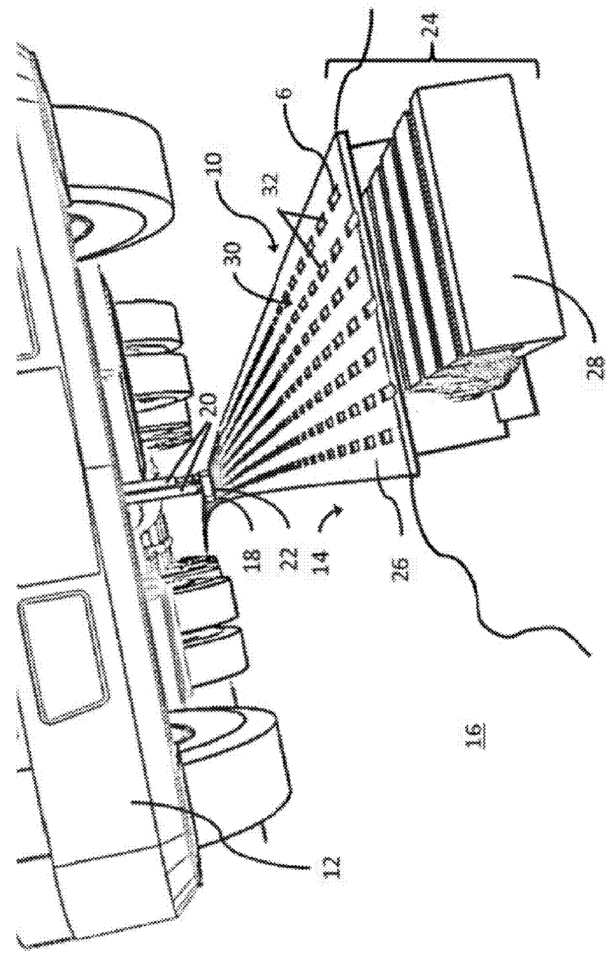
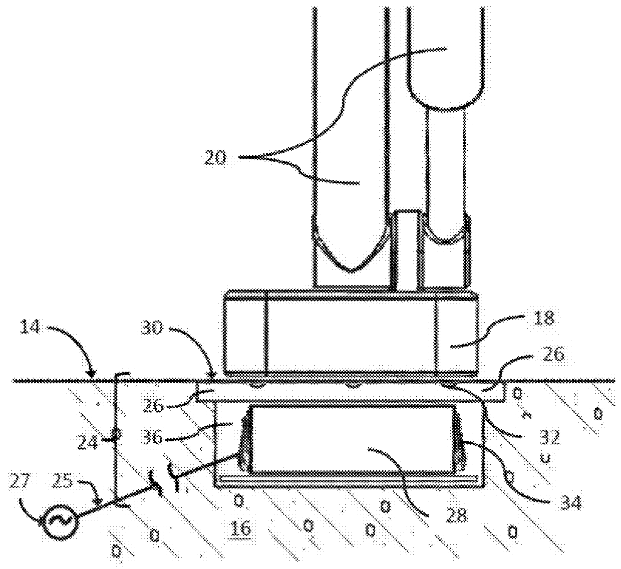
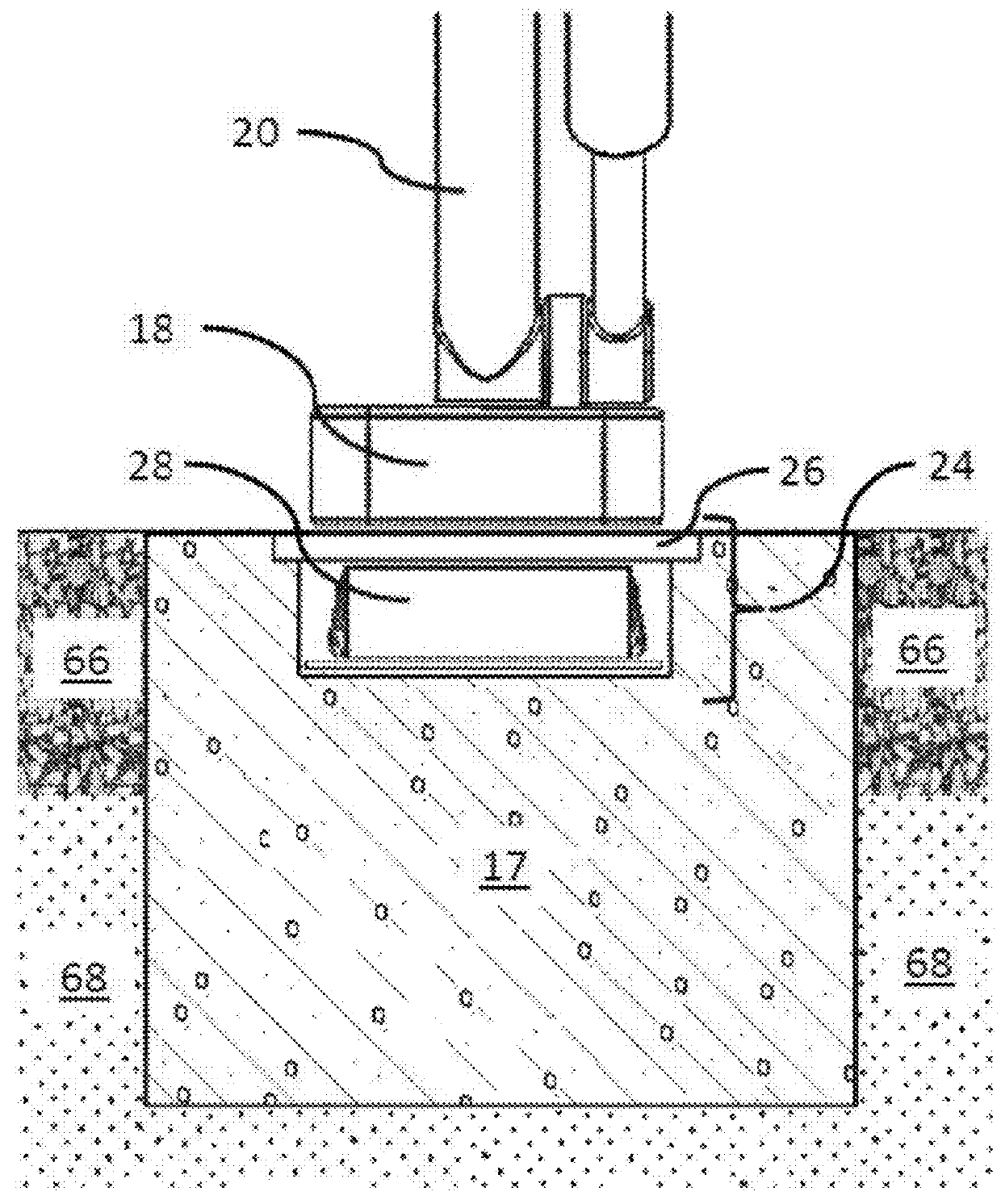
[0025]As used herein, the term “road bearing” has reference to an elongate structure that is positioned within a roadway structure. The road bearing is one of two surfaces, the other being the surface of the vehicle electric pickup device, which together create an air bearing. The road bearing can be aligned with the center of a vehicle travel lane, for example.

[0026]As used herein, the term, “road induction coils” h...


PUM


Abstract

A road bearing for inductive coupling to an electrical connection device of an electric vehicle includes a series of primary induction coils, a bearing surface element, and a plurality of deformation features in the bearing surface element. The series of primary induction coils are interconnected to a source of electrical power and disposed in a substantially linear array below a roadway surface and within a roadway structure, and are aligned generally parallel to an alignment of the roadway. The bearing surface element is disposed above the primary induction coils, and has an upper surface that is substantially flush with the roadway surface, has a surface flatness in the range of ±1 μm per 30 mm, and a magnetic permeability in the range of 0.9 to 2. The plurality of deformation features include depressions in the upper surface of the bearing surface element, and are configured to provide friction to vehicle wheels.

Description

CROSS-REFERENCE TO RELATED APPLICATIONS[0001]The present disclosure is related to U.S. Pat. No. 8,556,050, the disclosure of which is incorporated by reference herein in its entirety.BACKGROUND[0002]1. Field of the Invention[0003]The present disclosure relates generally to electric vehicles. More particularly, the present disclosure relates to a road bearing that is adapted for high-power inductive power transfer between an electric vehicle and a power source embedded in a roadway.[0004]2. Related Art[0005]Recent environmental, economic and geopolitical concerns have spurred significant interest and development in electric vehicles, and many advances have been made in electric vehicles in recent years. However, factors such as battery weight, cost, charging time and energy capacity still present significant hurdles to the widespread adoption and use of electric vehicles in place of those powered by internal combustion engines. While battery costs are dropping and energy densities ar...

Claims


Application Information

Patent Timeline
Patent Type & Authority Applications(United States)
IPC IPC(8): B60L5/00B60L5/40B60M1/04B60M1/34
CPCB60L5/005B60M1/34B60M1/04B60L5/40B60M7/003Y02T90/12Y02T10/7072Y02T90/14B60L53/12B60L53/30B60L53/39Y02T10/70
Inventor RICHARDS, BRYAN
Owner RICHARDS BRYAN
Why Eureka
Try Eureka