Process for cooling a hydrocarbon-rich fraction

a hydrocarbon-rich fraction and process technology, applied in the field of hydrocarbon-rich fraction processing, can solve the problems of no longer being used for generating the peak refrigeration and the cold expansion device, and achieve the effect of improving the partial load capacity and keeping the suction pressure of the compressor responsible for compressing the refrigerant high

Active Publication Date: 2016-02-25
LINDE AG
View PDF4 Cites 16 Cited by
  • Summary
  • Abstract
  • Description
  • Claims
  • Application Information

AI Technical Summary

Benefits of technology

[0018]It is energetically advantageous to keep the suction pressure of the compressor responsible for compressing the refrigerant as high as possible. If it is desired to avoid liquid in the work-producingly expanded second refrigerant substream and simultaneously keep as much liquid as possible in the expanded third refrigerant substream, defined boundary conditions result, which are met optimally by the proposed re

Problems solved by technology

The cold expander, however, in contrast to the processes of the p

Method used


Image

  • Process for cooling a hydrocarbon-rich fraction

Examples


Embodiment Construction

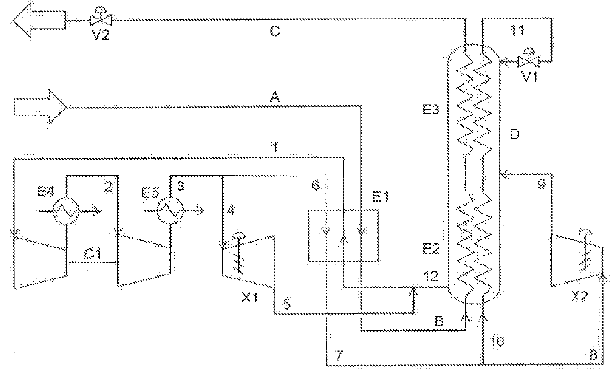
[0021]The hydrocarbon-rich gas fraction A that is to be cooled is cooled in the heat exchangers or heat exchanger zones E1, E2 and E3, and in the process optionally liquefied and subcooled or converted at a pressure above the critical pressure without a change of phase into a high-density fluid. In this case, the fraction that is to be liquefied is cooled (stream B) to the extent that, after the expansion in the valve V2 to a pressure of a maximum of 5 bar, preferably a maximum of 1.5 bar, predominantly liquid is formed, wherein the liquid fraction is at least 85 mol %, preferably at least 90 mol %.

[0022]The refrigeration circuit that serves to cool the hydrocarbon-rich fraction A, in addition to a single- or multistage compressor C1, has two expanders X1 and X2 and also an expansion valve V1. The refrigerant 1 circulating in this refrigeration circuit is compressed C1 in a multistage manner in the exemplary embodiment shown in FIG. 1, wherein corresponding intercoolers and aftercoo...


PUM


Abstract

A process for cooling a hydrocarbon-rich fraction, in particular natural gas, against a refrigerant circuit. In this process, the compressed refrigerant is divided into three refrigerant substreams. Whereas the first substream is work-producingly expanded in a warm expander and the second substream is work-producingly expanded in a cold expander, the third substream is work-producingly expanded at the lowest temperature level. The result therefrom is that the operating point of the cold expander is shifted in such a manner that the refrigeration output of the two expanders is situated in a ratio between 40/60 and 60/40.

Description

CROSS REFERENCE TO RELATED APPLICATIONS[0001]This application claims priority from DE Patent Application DE102014012316.2 filed on Aug. 19, 2014.BACKGROUND OF THE INVENTION[0002]The invention relates to a process for cooling a hydrocarbon-rich fraction, in particular natural gas.[0003]For the liquefaction of hydrocarbon-rich gas fractions, in particular natural gas, inter alia processes are employed in which the work-producing expansion of gases is utilized to generate refrigeration. To increase the thermodynamic efficiency, and thereby to reduce the specific energy consumption, more than one expansion turbine can be used. A shared characteristic of what are termed “multi-expander processes” is the separate provision of peak refrigeration (lowest refrigerant temperature) solely by sensible heat of a gas stream cooled by work-producing expansion and, independently thereof, the provision of the predominant part of the total required refrigeration output at a lower temperature level by...

Claims


Application Information

Patent Timeline
IPC IPC(8): F25J1/00F25B41/30
CPCF25J1/0022F25J1/005F25J1/0052F25J1/0092F25J1/0097F25J1/0212F25J1/0263F25J1/0288F25J1/0294F25J2270/16
Inventor BAUER, HEINZGOLLWITZER, CLAUDIA
Owner LINDE AG
Why Eureka
Try Eureka