Unlock instant, AI-driven research and patent intelligence for your innovation.

Method and apparatus for manufacturing a can end

Inactive Publication Date: 2016-03-03
CROWN PACKAGING TECH
View PDF5 Cites 2 Cited by
  • Summary
  • Abstract
  • Description
  • Claims
  • Application Information

AI Technical Summary

Benefits of technology

The present invention provides methods and apparatus for forming can ends by drawing and reforming a blank against a tool to create a shell, which is then reinforced to form a recessed structure. The methods involve holding the blank between inner and outer peripheral tool sets, and using an outer centre panel tool to draw the blank against it to form a shell. An inner centre panel tool is then used to reform the shell to have a centre panel and a recessed reinforcing structure extending around it. The apparatus includes the inner and outer peripheral tool sets, the outer centre panel tool, and the inner centre panel tool. The technical effects of the invention include improved can end strength and a more stable can end shape.

Problems solved by technology

However, the more complicated the can end structure, the greater the amount of processing which the material of the original blank has to undergo in order to be formed into the desired end shape.
The more the material is processed, the greater the amount of thinning that the material is likely to suffer due to the processing, in particular in the step of drawing the circular blank so as to form a can end shell.
Thinning of the material during drawing reduces the strength of the material locally where the thinning occurs.
Another result of excessive thinning of the material during the drawing and re-forming of the blank to form a can end is to exaggerate imperfections in the original blank material, which may lead to localised failure of the can end.
As a result, unless very high quality control systems are put in place, it is hard to maintain the production of such can ends within desired tolerances, such that an unacceptably high number of defective can ends may be produced.
However, since the presence or otherwise of imperfections and inhomogeneities in the blank material from which the can ends are made is an entirely random phenomenon, they cannot readily be predicted, and so any can end design or manufacturing process which results in the production of defective can ends in this manner is not acceptable.

Method used


Image

  • Method and apparatus for manufacturing a can end
  • Method and apparatus for manufacturing a can end
  • Method and apparatus for manufacturing a can end

Examples


Embodiment Construction

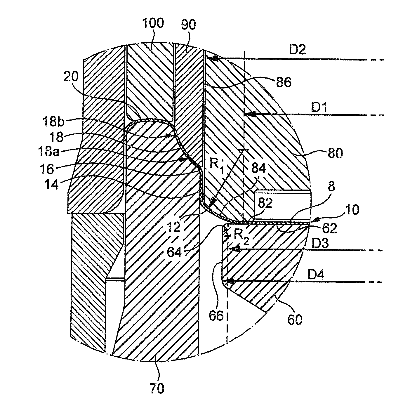
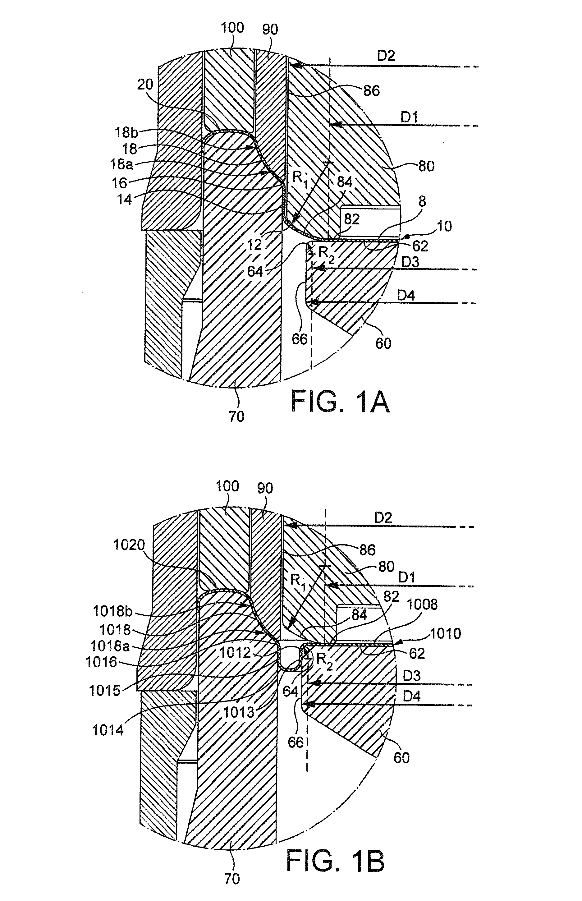
[0052]In the following description, a can end is formed from a circular blank of material, exhibiting a central axis of rotational symmetry. This axis of the blank corresponds to the central axes of a can end shell and of a can end formed from the blank, and is used throughout the present description to define the axial direction of the blank, of the can end shell, the can end, and a can having the can end attached to a body of the can, as well as to the central axis of the associated tools and tooling by which the can end may be formed. In the embodiments illustrated and described herein, these all have a common central axis.

[0053]The upper sides of the can ends shown in FIGS. 1B, 2B, 3B, 4B, 5B, 6B, 7B, 8B, 9B, 10B and 11B correspond to the sides of the can ends which will be exposed, externally, after each can ends has been joined to one axial end of a can body. Similarly, the lower sides of the can ends shown in FIGS. 1B, 2B, 3B, 4B, 5B, 6B, 7B, 8B, 9B, 10B and 11B correspond to...


PUM

PropertyMeasurementUnit
Lengthaaaaaaaaaa
Lengthaaaaaaaaaa
Fractionaaaaaaaaaa

Abstract

There is disclosed herein a method of forming a can end comprising: holding a peripheral portion of a blank between inner (60, 70) and outer (80, 90, 100) peripheral tool sets; drawing a central portion of the blank against an outer centre panel tool (80) having a central region and a sloping peripheral edge (84) extending to a peripheral wall (86) by moving the outer centre panel tool (80) inwardly relative to the peripheral tool sets to form a drawn can end shell (10); and reforming the can end shell (10) against an inner centre panel tool (60) having a central region and a peripheral region by moving the inner centre panel tool (60) outwardly relative to the peripheral tool sets to reform the drawn central portion to have a centre panel defined by the central region of the inner centre panel tool (60) and a recessed reinforcing structure extending around the centre panel, wherein the sloping peripheral edge (84) of the outer centre panel tool (80) has a convex radius of curvature of 2 mm or more and 30 mm or less between the central region of the outer centre panel tool (80) and the peripheral wall (86) of the outer centre panel tool (80). A related apparatus is also disclosed.

Description

FIELD[0001]This invention relates to metal packaging and more particularly to a method and apparatus for manufacturing a can end, as well as to related can ends and to can end shells which can be re-formed into such can ends. The invention is particularly concerned with the manufacture of can ends for carbonated drinks cans.BACKGROUND[0002]In a typical conventional method of manufacturing can ends, a sheet metal blank is positioned between a pair of dies which are moved to shear an edge of the blank, after which a punch descends to draw the now circular blank about an annular ring into a can end shell having a peripheral flange, a frustoconical wall, and an end panel connected to the frustoconical wall by an annular curved or radiused wall portion defining a radius of curvature between the frustoconical wall and the end panel. The can end shell is then removed from the first set of dies and inserted into a second set of dies, in which the peripheral flange is curled into a downward ...

Claims


Application Information

Patent Timeline
IPC IPC(8): B21D51/44B65D1/16
CPCB65D1/16B21D51/44
Inventor DUNWOODY, PAUL, ROBERTLOCKLEY, ANDREW, ROBERTMARRIOT, PHILIP, ALANOSBORN, STEPHEN, JOHN
Owner CROWN PACKAGING TECH