Impact resistant lock and tilt latch combination for a sliding sash window

a technology of sliding sash window and latch, which is applied in the direction of building locks, constructions, fastening means, etc., can solve the problems of window hardware, moisture and debris entering the interior of the dwelling, and the design of the window

Active Publication Date: 2016-03-03
VISION INDS GROUP
View PDF26 Cites 3 Cited by
  • Summary
  • Abstract
  • Description
  • Claims
  • Application Information

AI Technical Summary

Benefits of technology

[0007]It is an object of the invention to provide a sash lock to prevent relative sliding m

Problems solved by technology

However, this arrangement relies solely upon the tilt latch at the top of the sliding sash window and the pivotal attachment at the bottom of the sash member to provide the structural integrity needed to resist high wind loads, since the sash frame itself is not nested within the track of the master window frame.
This significant deformation under such high wind loads creates a serious problem for the window hardware, particularly the tilt latch, as the latch member merely being biased into the master window frame track does not serv

Method used


Image

  • Impact resistant lock and tilt latch combination for a sliding sash window
  • Impact resistant lock and tilt latch combination for a sliding sash window
  • Impact resistant lock and tilt latch combination for a sliding sash window

Examples


Embodiment Construction

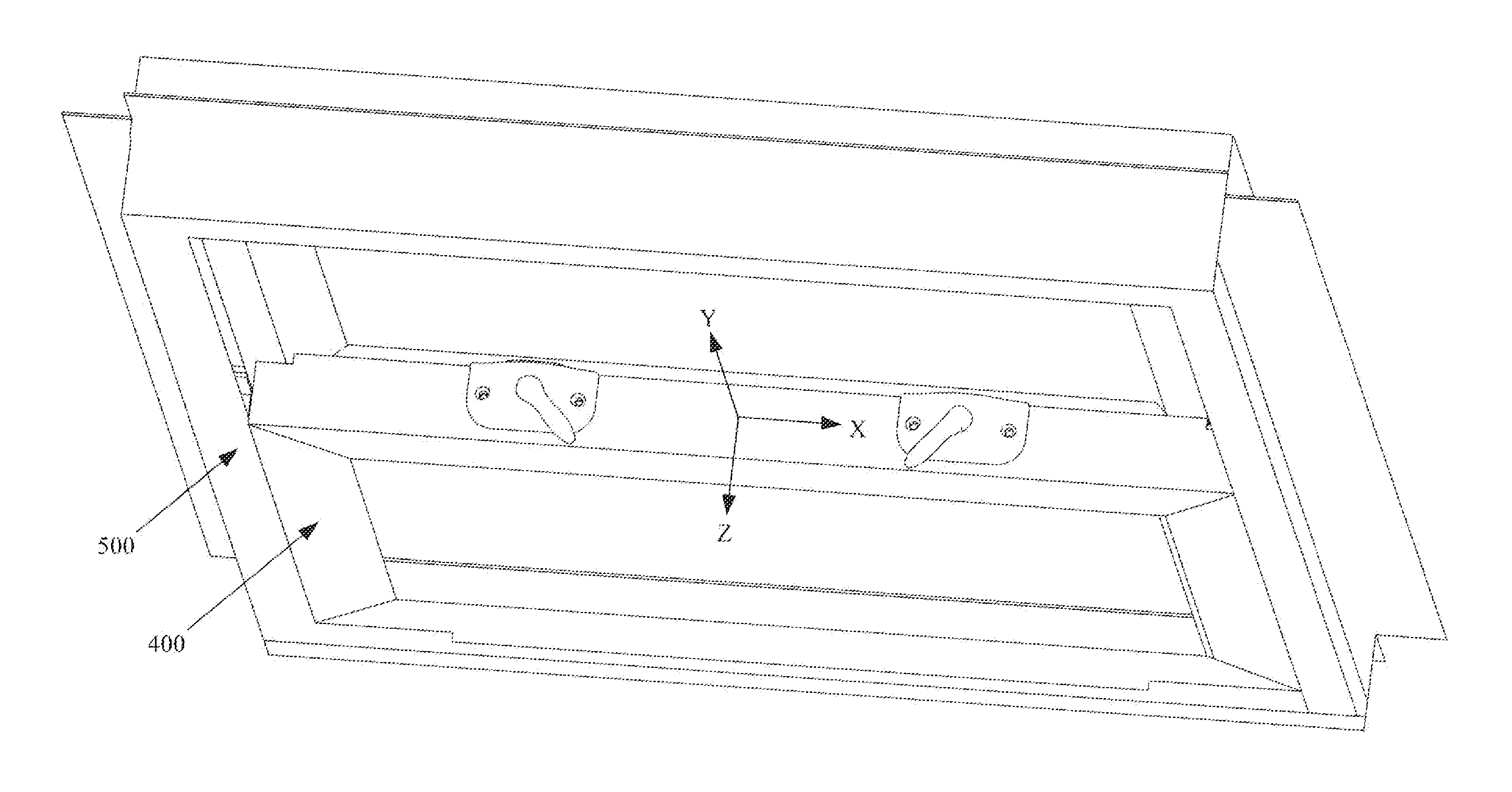
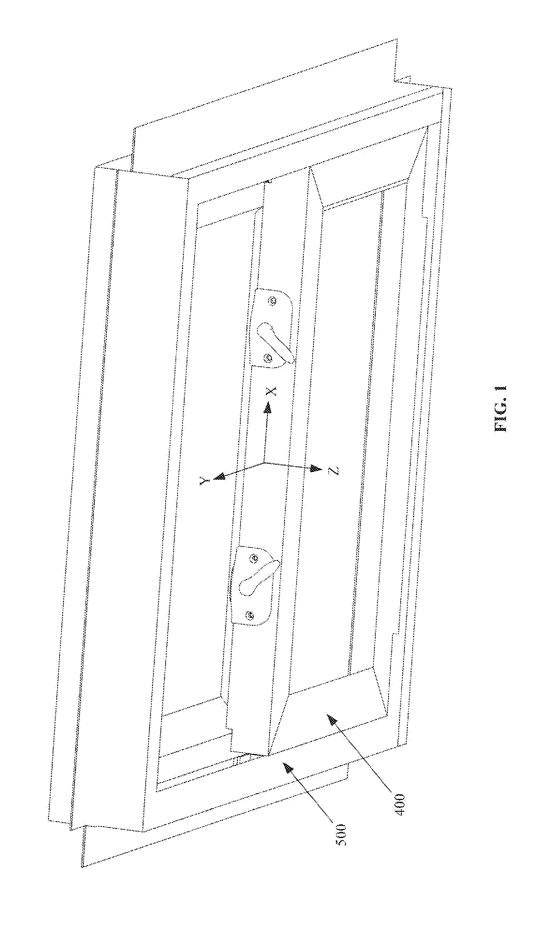
[0088]FIG. 1 shows a left-hand and a right-hand integrated sash lock / tilt latch fastener of the present invention installed with respect to a sliding sash window 400 that is slidably disposed in a master window frame 500. To simplify the presentation herein, the following disclosure is directed only to the left-hand fastener shown in FIG. 1, since the right-hand fastener is a mirrored version of the left-hand fastener, being principally made up of mirror image parts.

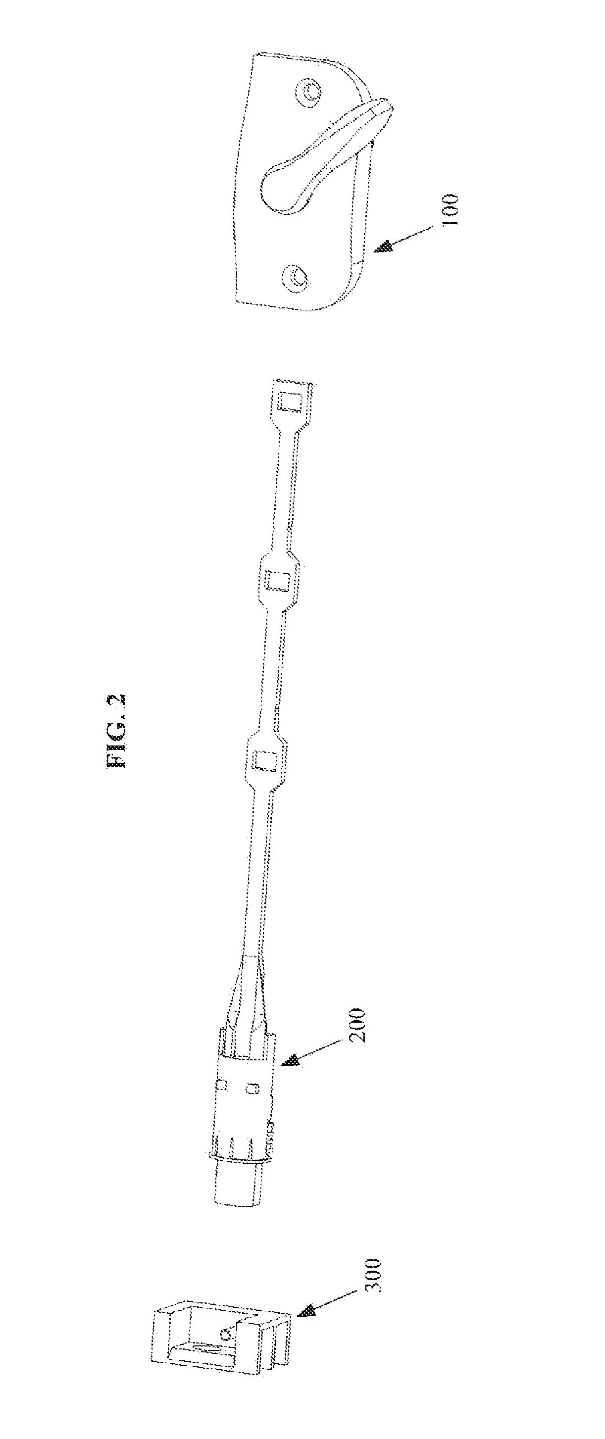
[0089]The left-hand integrated sash lock / tilt latch fastener, as seen in FIG. 2, may include a lock assembly 100, a latch assembly 200, and a fitting assembly 300. The latch assembly 200 may be blindly mated to the lock assembly 100 during installation of each with respect to the sash window 400.

[0090]As seen in the exploded view of FIG. 19, the sash lock assembly 100 may include a housing 10, a shaft / handle member 40, a cam 50, a lever arm 70, and a pair of identical leaf springs 90 / 90′.

[0091]Perspective views of the ho...


PUM


Abstract

A sash window fastener includes lock and latch assemblies, and a fitting. The lock mounts upon the meeting rail, and includes a pivotable cam to engage a keeper on the master frame, and a pivotable arm acting as a follower. The arm interconnects with the latch within the meeting rail, so cam rotation controls arm positioning—causing translation of the latch. The cam can occupy three positions causing three corresponding latch positions: an extended position securing the cam to the keeper, with the latch engaging the master frame to prevent tilting, and also receiving a post of the fitting therein to further secure the window against impact loading; a first retracted position disengaging the cam from the keeper, and permitting sliding of the window into an open position that also elevates the latch member above the post; and a second retracted cam position causing latch member retraction that permits tilting.

Description

CROSS REFERENCE TO RELATED APPLICATIONS[0001]This application is a continuation-in-part of U.S. patent application Ser. No. 14 / 566,908, filed on Dec. 11, 2014, having the title “Integrated Sash Lock and Tilt Latch Combination with Improved Wind-Force-Resistance Capability,” which is a continuation-in-part of U.S. patent application Ser. No. 14 / 278,226, filed on May 15, 2014, having the title “Integrated Sash Lock and Tilt Latch Combination with Improved Interconnection Capability Therebetween.” which is a continuation-in-part of U.S. patent application Ser. No. 14 / 198,986, filed on Mar. 6, 2014, having the title “Integrated Sash Lock and Tilt Latch with Screwless Installation and Removal from Meeting Rail,” with the disclosures of each being incorporated herein by reference.FIELD OF THE INVENTION[0002]The present invention relates to improvements in locks and tilt latches for slidable sash windows (or doors), and more particularly to improvements to an integral sash lock / tilt latch ...

Claims


Application Information

Patent Timeline
IPC IPC(8): E05C1/14E05C9/02
CPCE05C1/14E05C9/028E05B65/0841E05C1/12E05C3/045E05C9/20E05C2007/007Y10T292/0977E05B9/08
Inventor LIANG, LUKECHEN, DAVIDPAESANO, GLEN
Owner VISION INDS GROUP
Why Eureka
Try Eureka