
Liquid crystal display

a liquid crystal display and display technology, applied in the field of display devices, can solve chroma deterioration, and approach still has some drawbacks, and achieve the effect of improving the aperture ratio of the pixel area and solving the problems of color shift and chroma deterioration

Active Publication Date: 2016-03-03
INNOLUX CORP
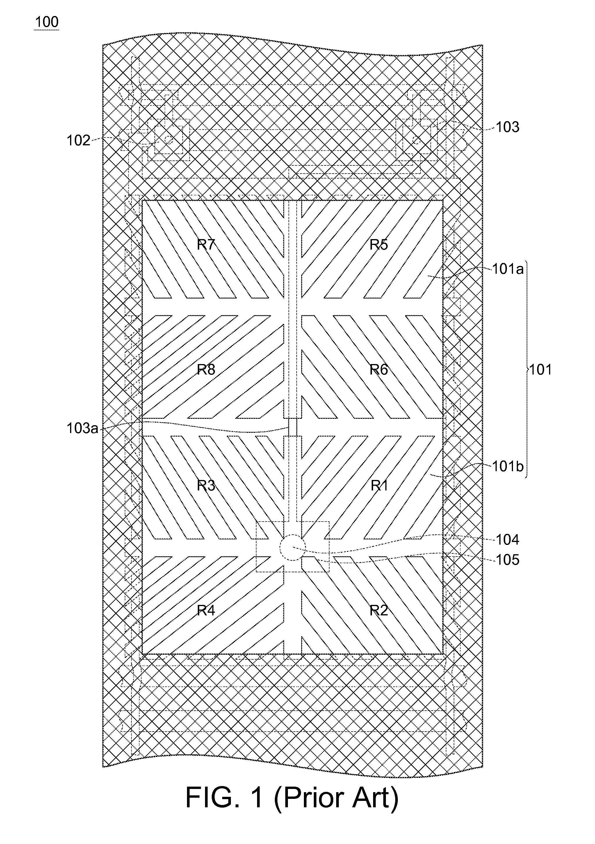
View PDF1 Cites 5 Cited by
  • Summary
  • Abstract
  • Description
  • Claims
  • Application Information

AI Technical Summary

Benefits of technology

The patent describes a LCD screen with multiple small electrodes in the pixel area to improve color accuracy and prevent fading. The design also includes a via hole that connects to one of the electrodes, but it is placed outside of the pixel area to increase the aperture ratio and prevent light from leaking. The technical effect of this design is improved image quality and reduced color distortion.

Problems solved by technology

As a result, color shift may occur and chroma (saturation) of the MVA LCD may be deteriorated.
But this approach still has some drawbacks.

Method used


Image

  • Liquid crystal display
  • Liquid crystal display
  • Liquid crystal display

Examples


Embodiment Construction

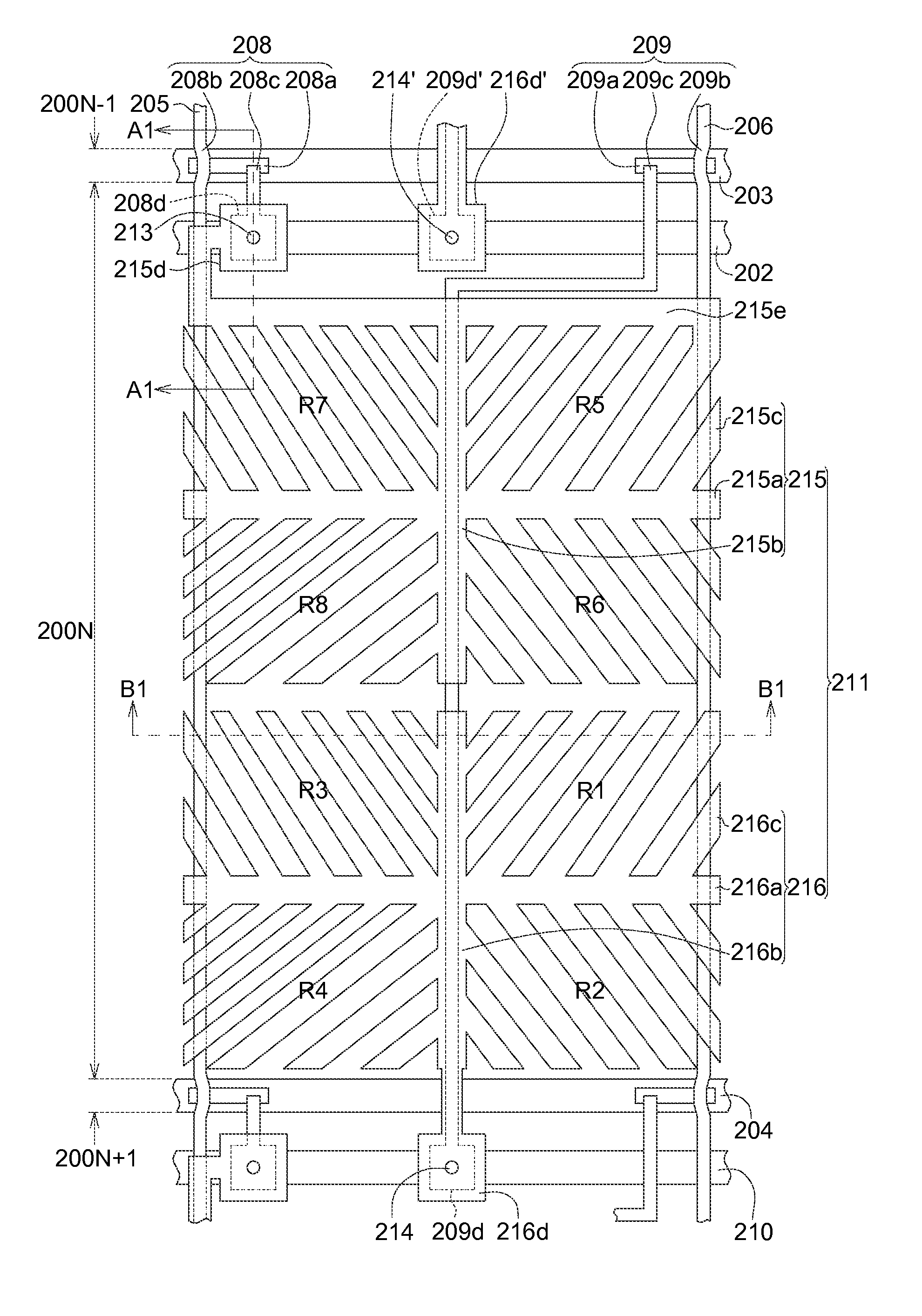
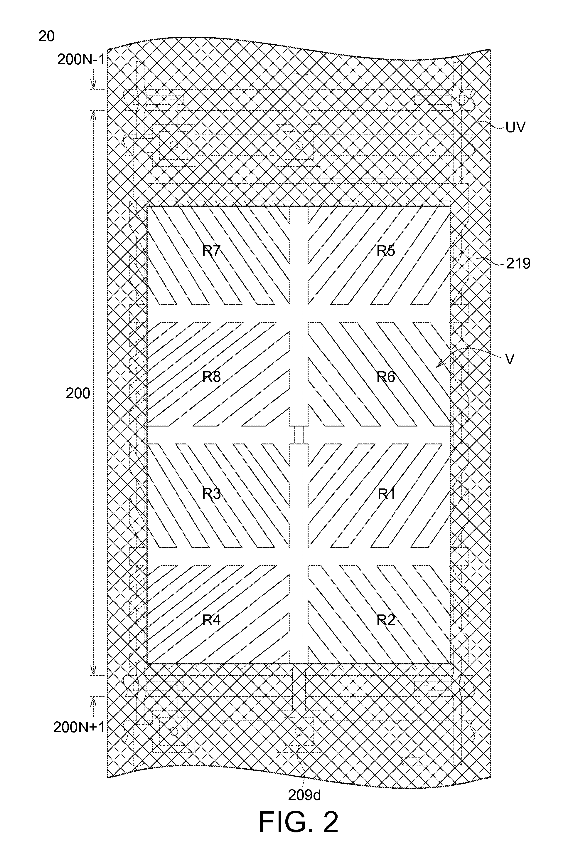
[0020]The embodiments as illustrated below provide an LCD to solve the problems of color shift and chroma deterioration as well as to increase the aperture ratio of the pixel area of the LCD. The present invention will now be described more specifically with reference to the following embodiments illustrating the structure and method for fabricating the memory device.

[0021]It is to be noted that the following descriptions of preferred embodiments of this invention are presented herein for purpose of illustration and description only. It is not intended to be exhaustive or to be limited to the precise form disclosed. Also, it is also important to point out that there may be other features, elements, steps and parameters for implementing the embodiments of the present disclosure which are not specifically illustrated. Thus, the specification and the drawings are to be regard as an illustrative sense rather than a restrictive sense. Various modifications and similar arrangements may be...


PUM

PropertyMeasurementUnit
thicknessaaaaaaaaaa
thicknessaaaaaaaaaa
areaaaaaaaaaaa

Abstract

An LCD comprises a first scan line, a second scan line, a first data line, a second data line, a pixel area, a first sub-pixel electrode and a first active element. The first scan line has a first sidewall; the second scan line has a second sidewall adjacent to the first sidewall; and the first data line has a third sidewall intersecting with the first sidewall and the second sidewall. The second data line has a fourth sidewall adjacent to the third sidewall. The pixel area is an area defined by the first sidewall, the second sidewall, the third sidewall and the fourth sidewall. The first sub-pixel is partially disposed in the pixel area. The first active element has a first electrode electrically connected to the first sub-pixel electrode through a first via hole, wherein a portion of the first via hole is disposed out of the pixel area.

Description

[0001]This application claims the benefit of Taiwan application Serial No. 103130087, filed Sep. 1, 2014, the subject matter of which is incorporated herein by reference.BACKGROUND[0002]1. Technical Field[0003]The disclosure in generally relates to a display device and more particularly to a liquid crystal display (LCD).[0004]2. Description of the Related Art[0005]Currently, the design of LCDs is trending towards to offer high luminance, high contrast ratio and wide viewing angle. Several technologies for improving the viewing angle of an LCD have been provided to satisfy the design requirements. A multi-domain vertical alignment liquid crystal display (MVA LCD) is a common type of LCD with wide viewing angle.[0006]A MVA LCD typically has a plurality of alignment protrusions or slits disposed above a substrate with thin film transistor (TFT) array formed thereon, and used to direct the liquid crystal molecule tilting in various directions, whereby a plurality of alignment domains, e...

Claims


Application Information

Patent Timeline
Patent Type & Authority Applications(United States)
IPC IPC(8): G02F1/1343G02F1/1362H01L23/522H01L27/12
CPCG02F1/134309H01L27/124H01L27/1255G02F2001/134345G02F1/136286G02F1/136227H01L23/5226G02F1/13624G02F1/134345
Inventor YANG, CHING-CHE
Owner INNOLUX CORP
Learn More