Radio frequency coupling structure and a method of manufacturing thereof

a technology of frequency coupling and coupling structure, applied in the direction of waveguides, instruments, and reradiation, can solve the problem that rf signals may not be transmittable with sufficient strength

Active Publication Date: 2016-03-03
NXP USA INC
View PDF1 Cites 12 Cited by
  • Summary
  • Abstract
  • Description
  • Claims
  • Application Information

AI Technical Summary

Problems solved by technology

The RF signal may be attenuated during the transfer from the first radiating element to the second radiating element in a way such that the RF signal may not be transmittable with sufficient strength.

Method used


Image

  • Radio frequency coupling structure and a method of manufacturing thereof
  • Radio frequency coupling structure and a method of manufacturing thereof
  • Radio frequency coupling structure and a method of manufacturing thereof

Examples


Embodiment Construction

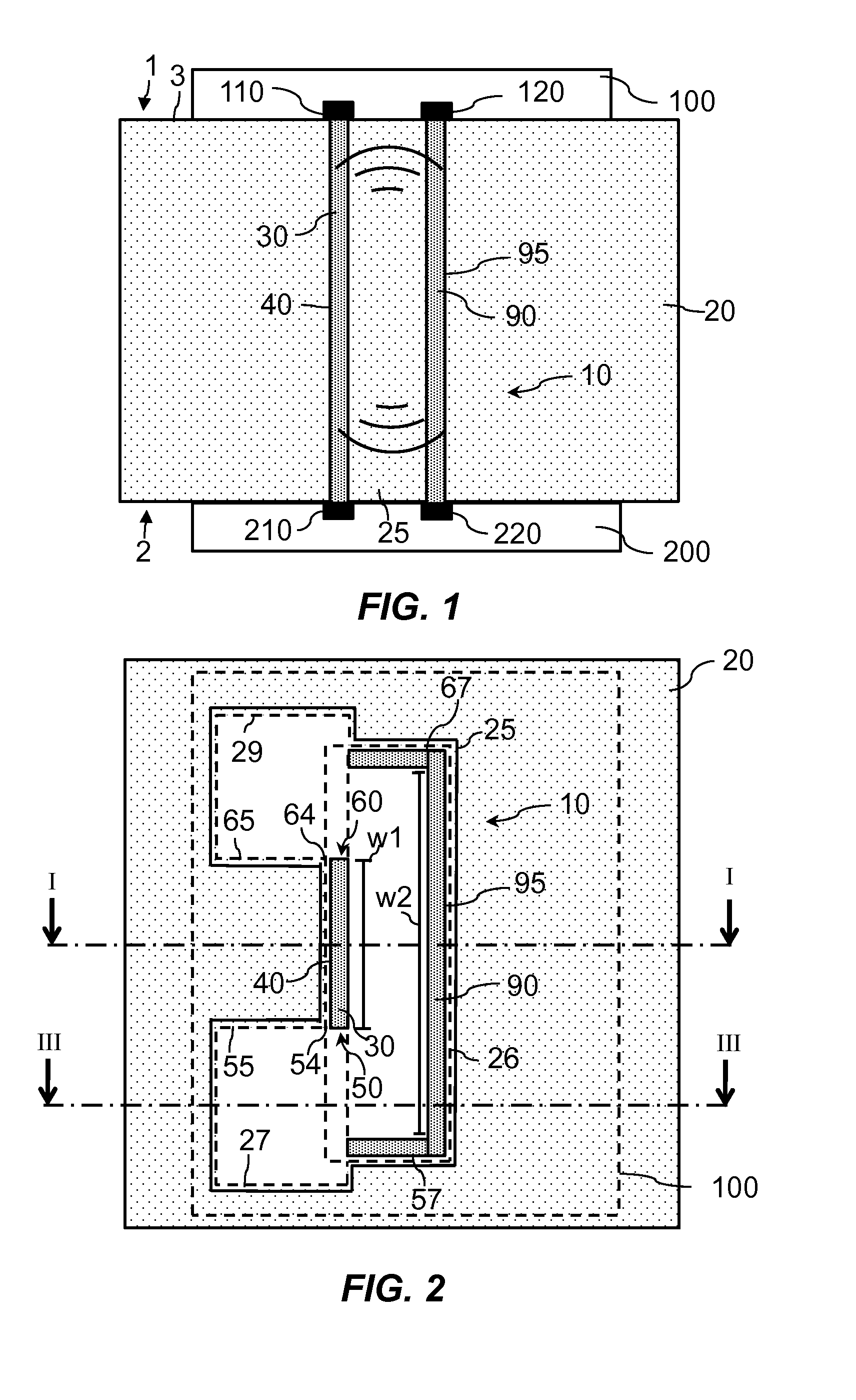
[0022]An example of a radio frequency (RF) transmission structure 10 will be hereinafter described with reference to FIG. 1 and FIG. 2.

[0023]FIG. 1 shows a cross section of the RF coupling structure 10 taken along the line I-I in FIG. 2.

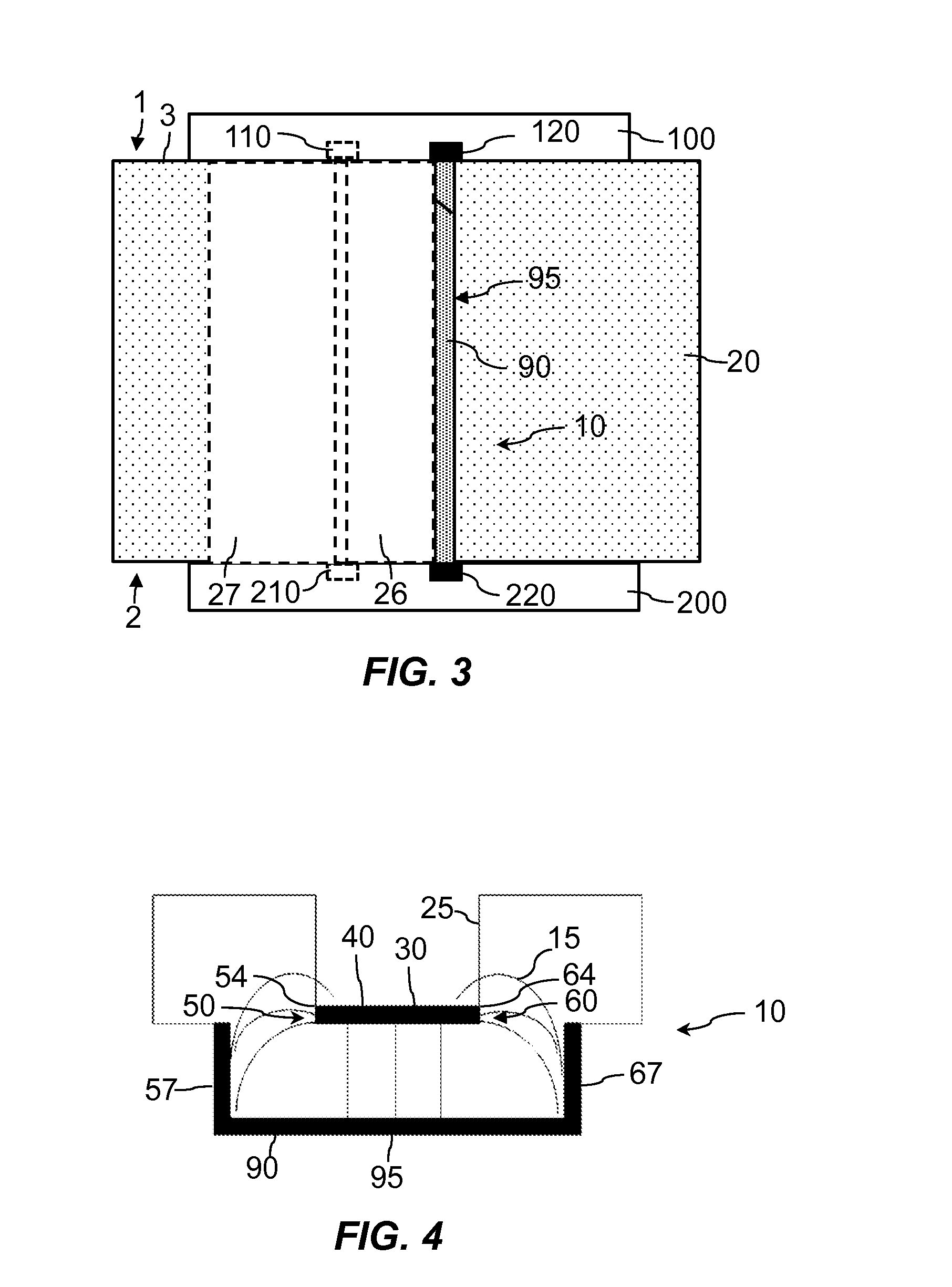
[0024]FIG. 2 shows a cross section of the RF coupling structure 10 along a plane parallel to a surface 3 of FIG. 1.

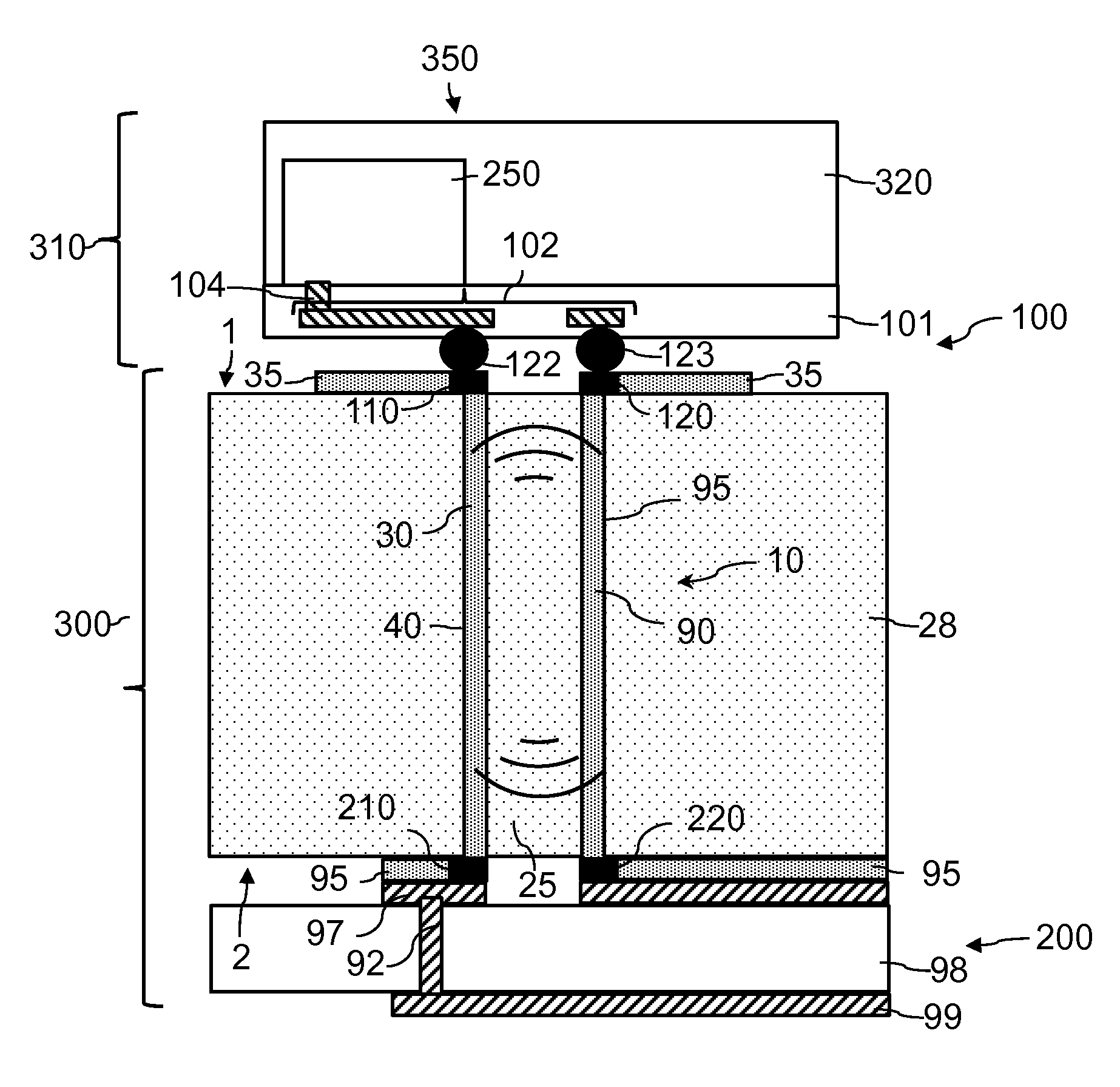
[0025]With reference to FIG. 1, the RF coupling structure 10 couples a RF signal between a first radiating element 100 and a second radiating element 200. The first radiating element 100 is arranged at a first side 1 of a first dielectric substrate 20. The second radiating element 200 is arranged at a second side 2 of the first dielectric substrate 20. The second side 2 is opposite to the first side 1. The RF coupling structure 10 comprises a hole 25 arranged through the first dielectric substrate 20 and extending from the first side 1 to the second side 2. The hole 25 is provided in the first dielectric substrate 20. The RF coupling str...


PUM


Abstract

A radio frequency transmission structure couples a RF signal between a first and a second radiating elements arranged at a first and a second sides of a first dielectric substrate, respectively. The RF coupling structure comprises: a hole arranged through the first dielectric substrate, a first electrically conductive layer arranged on a first wall of the hole to electrically connect a first and a second signal terminals, a second electrically conductive layer arranged on a second wall of the hole opposite to the first wall to electrically connect a first and a second reference terminals. The first electrically conductive layer is separated from the second electrically conductive layer. The hole extends beyond the first wall away from the second wall.

Description

FIELD OF THE INVENTION[0001]This invention relates to a radio frequency coupling structure, a printed circuit board, a radio frequency device, a radar sensor and to a method of manufacturing the radio frequency coupling structure.BACKGROUND OF THE INVENTION[0002]Radio frequency (RF) coupling structures may be used to couple a RF signal from one side to another side of a RF device. The RF signal may for example be transmitted from a first radiating element to a second radiating element via the RF coupling structure. Alternatively, in a reciprocal path, the RF signal may be received by the second radiating element and transmitted via the RF structure to the first radiating element. The first radiating element and the second radiating element may be for example an antenna, a waveguide, a transmission line coupled to the RF coupling structure. The RF signal may be attenuated during the transfer from the first radiating element to the second radiating element in a way such that the RF si...

Claims


Application Information

Patent Timeline
Patent Type & Authority Applications(United States)
IPC IPC(8): H01P3/02G01S7/02G01S13/02G01S13/931H01P11/00H05K1/02
CPCH01P3/026H05K1/0213H01P11/003G01S13/02G01S7/02H01P3/121H01P5/024G01S7/03G01S13/931H05K1/0243H05K1/0274H05K1/144H05K2201/0187H05K2201/041H05K2201/09854H05K2201/09981
Inventor QIANG, LIHARTIN, OLIN, LEEREUTER, RALFTONG, ZIQIANG
Owner NXP USA INC
Why Eureka
Try Eureka