Electrical receptacle connector

Active Publication Date: 2016-03-03
ADVANCED CONNECTEK INC
View PDF1 Cites 22 Cited by
  • Summary
  • Abstract
  • Description
  • Claims
  • Application Information

AI Technical Summary

Benefits of technology

[0008]In conclusion, the grounding sheet is in contact with the ground terminal of the upper-row terminals or the ground terminal of the lower-row terminals through the protruded portions, so that the noises among the signal terminals are effectively conducted and grounded through the ground terminals. Alternatively, since the grounding sheet is connected to the ground of a circuit board to conduct and ground the noises, the noises and the crosstalk interferences of the electrical receptacle connector can be reduced. Additionally, because the grounding sheet is sandwiched between the upper-row terminals and the lower-row terminals, and the grounding terminals are respectively located at the outermost portions of the upper-row terminals and lower-row terminals, the signal terminals are grounded so that the crosstalk interferences among the signal terminals can be reduced. Next, the structural strength of the tongue portion can be improved by the assembly of the grounding sheet and the tongue portion. Furthermore, since the through hole is opened on the bottom plane of the first mount, the protruded portion extends out of the through hole to contact the ground terminal of the upper-row terminals, and sufficient contact between the ground termi

Problems solved by technology

The transmission rate of USB 2.0 is insufficient.
Consequently, upon transmitting high-frequency signals, interference from the crosstalk between the terminals would easily a

Method used


Image

  • Electrical receptacle connector
  • Electrical receptacle connector
  • Electrical receptacle connector

Examples


Example

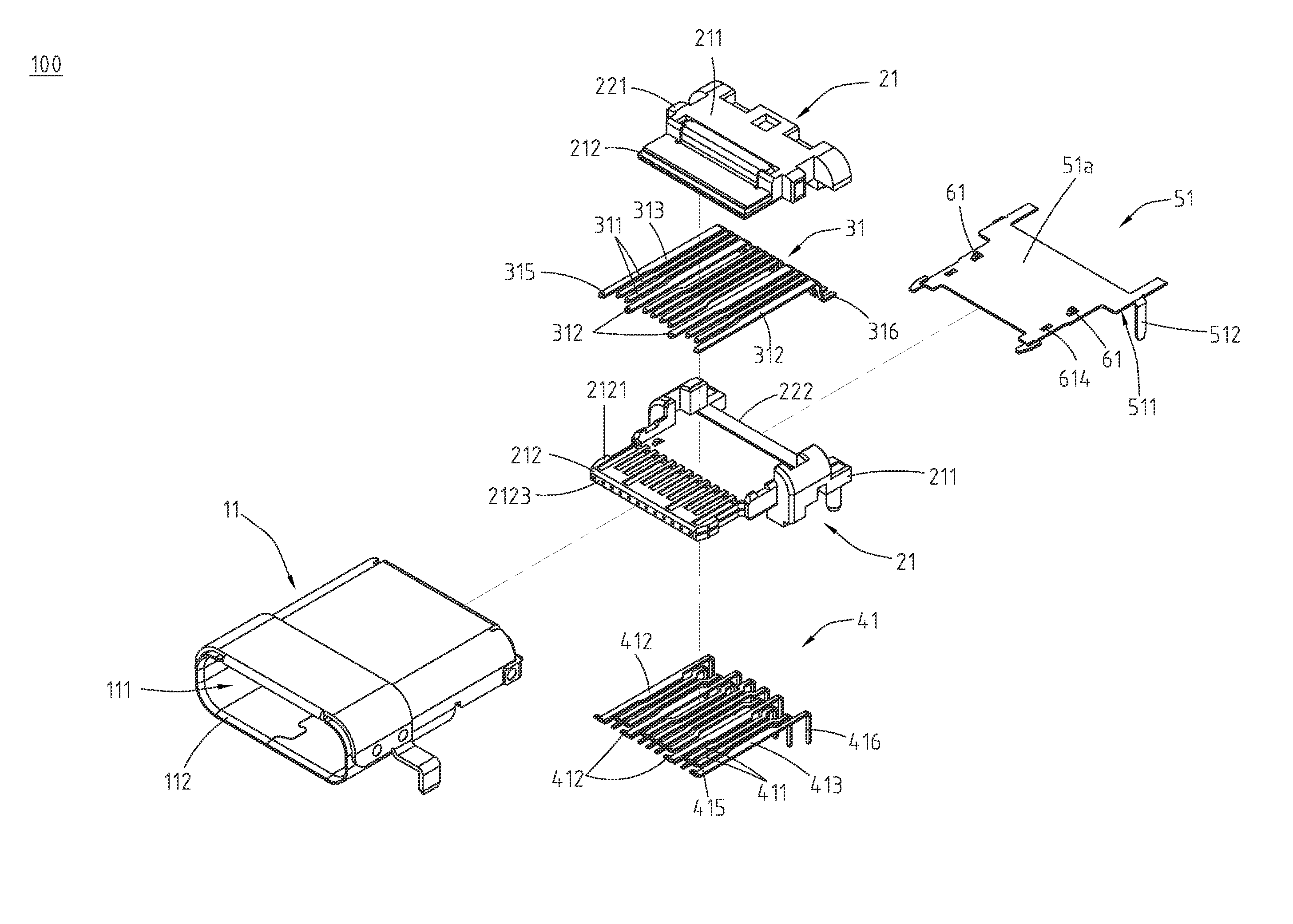
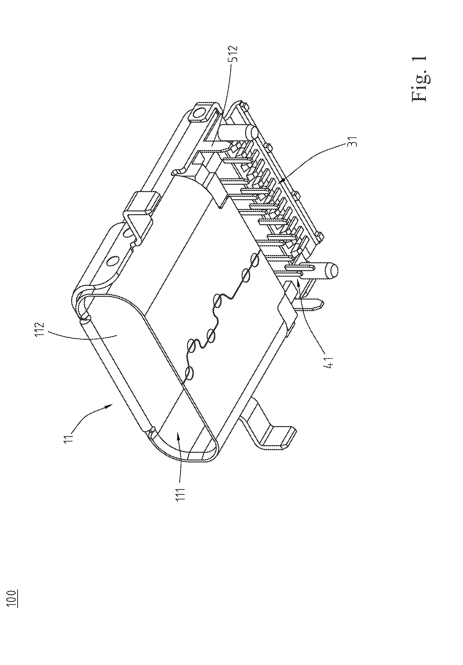
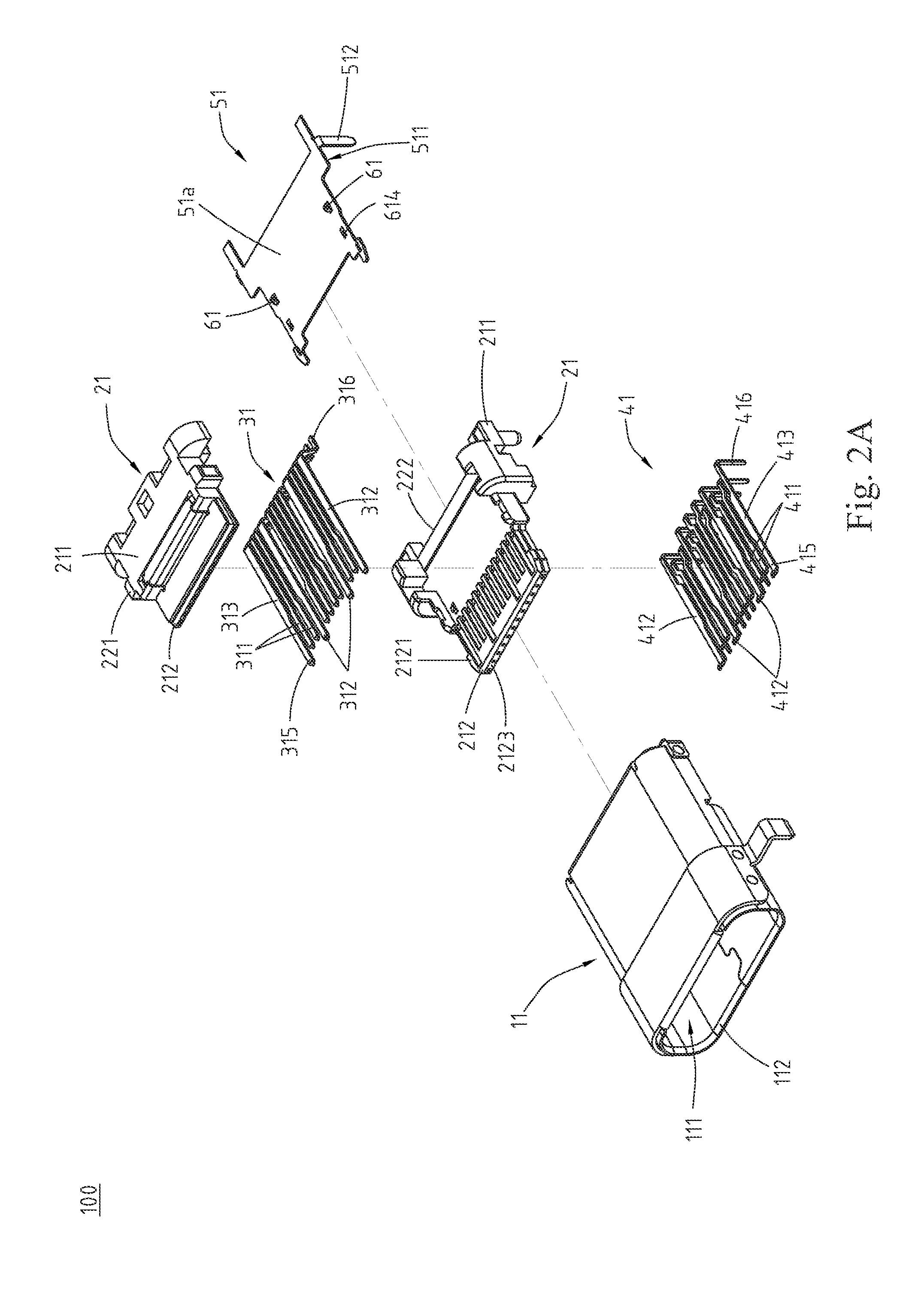
[0022]Please refer to FIG. 1, FIG. 2A and FIG. 3, which illustrate an exemplary embodiment of an electrical receptacle connector 100 according to the instant disclosure. FIG. 1 is a perspective view of an electrical receptacle connector 100 according to an exemplary embodiment of the instant disclosure. FIG. 2A is a front exploded view of the electrical receptacle connector 100 of the exemplary embodiment. FIG. 3 is a back exploded view of the electrical receptacle connector 100 of the exemplary embodiment in which the metallic shell 11 is omitted. The electrical receptacle connector 100 described herein provides a USB Type-C connection interface. In this embodiment, the electrical receptacle connector 100 comprises a metallic shell 11, an insulated housing 21, a plurality of upper-row terminals 31, a plurality of lower-row terminals 41, and a grounding sheet 51.

[0023]Please refer to FIG. 1 and FIG. 2A, in which the metallic shell 11 is a hollowed shell and a receptacle cavity 111 i...


PUM


Abstract

An electrical receptacle connector includes an insulated housing, upper-row terminals, lower-row terminals, and a grounding sheet. The insulated housing includes a base portion and a tongue portion. The tongue portion is extended from one side of the base portion and has an upper surface and a lower surface. The upper-row terminals are disposed at the base portion and the tongue portion and include a ground terminal located at the upper surface The lower-row terminals are disposed at the base portion and the tongue portion and include a ground terminal located at the lower surface. The grounding sheet is disposed at the insulated housing and located between the ground terminal of the upper-row terminals and the ground terminal of the lower-row terminals. The grounding sheet includes one or more protruded portion in contact with the ground terminal of the upper-row terminals or the ground terminal of the lower-row terminals.

Description

CROSS-REFERENCES TO RELATED APPLICATIONS[0001]This non-provisional application claims priority under 35 U.S.C. §119(a) on Patent Application No. 103130043 filed in Taiwan, R.O.C. on 2014 Aug. 29, the entire contents of which are hereby incorporated by reference.FIELD OF THE INVENTION[0002]The instant disclosure relates to an electrical connector, and more particular to an electrical receptacle connector.BACKGROUND[0003]Generally, Universal Serial Bus (USB) is a serial bus standard to the PC architecture with a focus on computer interface, consumer and productivity applications. The existing Universal Serial Bus (USB) interconnects have the attributes of plug-and-play and ease of use, from the end user's point of view. Now, as technology innovation marches forward, new kinds of devices, media formats and large inexpensive storage products are converging. They require significantly more bus bandwidth to maintain the interactive experience that users have come to expect. In addition, u...

Claims


Application Information

Patent Timeline
IPC IPC(8): H01R13/6471H01R24/60
CPCH01R13/6471H01R2107/00H01R24/60H01R12/724H01R13/6461H01R13/6596
Inventor KAO, YA-FENTSAI, YU-LUNHOU, PIN-YUANLIAO, CHUNG-FUTSAI, WEN-HSIEN
Owner ADVANCED CONNECTEK INC
Why Eureka
Try Eureka