Supercharge Your Innovation With Domain-Expert AI Agents!

Frame and display device using same

a display device and frame technology, applied in the field of frames and display devices, can solve the problems of frame failure to meet the requirements of slim design, difficult to determine the size of reserved gaps, easy movement of panels in the frame, etc., and achieve the effect of convenient assembly

Active Publication Date: 2016-03-03
SHENZHEN CHINA STAR OPTOELECTRONICS TECH CO LTD
View PDF2 Cites 5 Cited by
  • Summary
  • Abstract
  • Description
  • Claims
  • Application Information

AI Technical Summary

Benefits of technology

The present invention provides a frame and display panel that have a rotating part in the side frames to guide the display panel in the frame. This makes it easy to assemble the display panel in the frame even if there is a small gap between the frame and the display panel. The technical effect is improved assembly ease and convenience.

Problems solved by technology

However, a size of the reserved gap is difficult to determine.
If the reserved gap is too large, the display panel assembled in the frame is easy to move and the frame fails to satisfy a slim design demands.
If the reserved gap is too small, the display panel is difficult to be assembled in the frame.

Method used


Image

  • Frame and display device using same
  • Frame and display device using same
  • Frame and display device using same

Examples


first embodiment

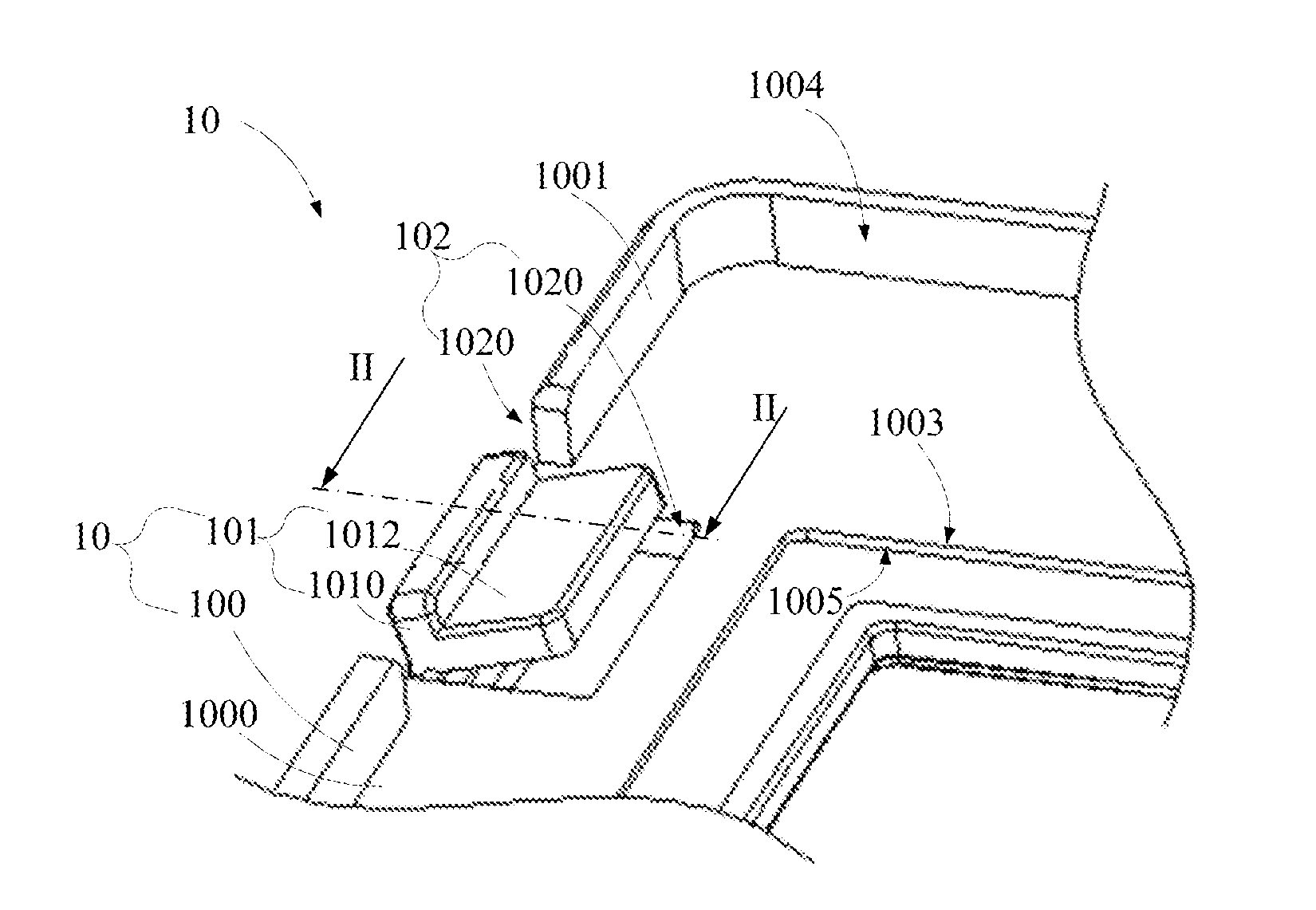
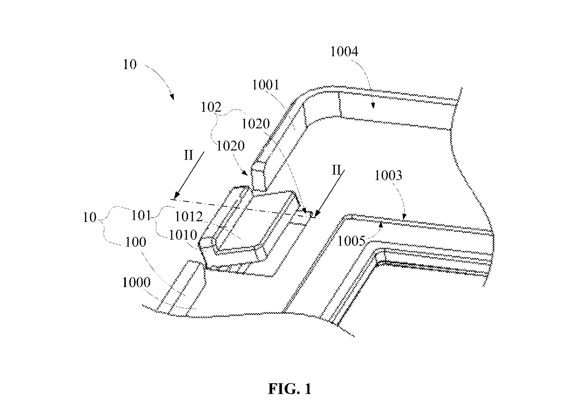
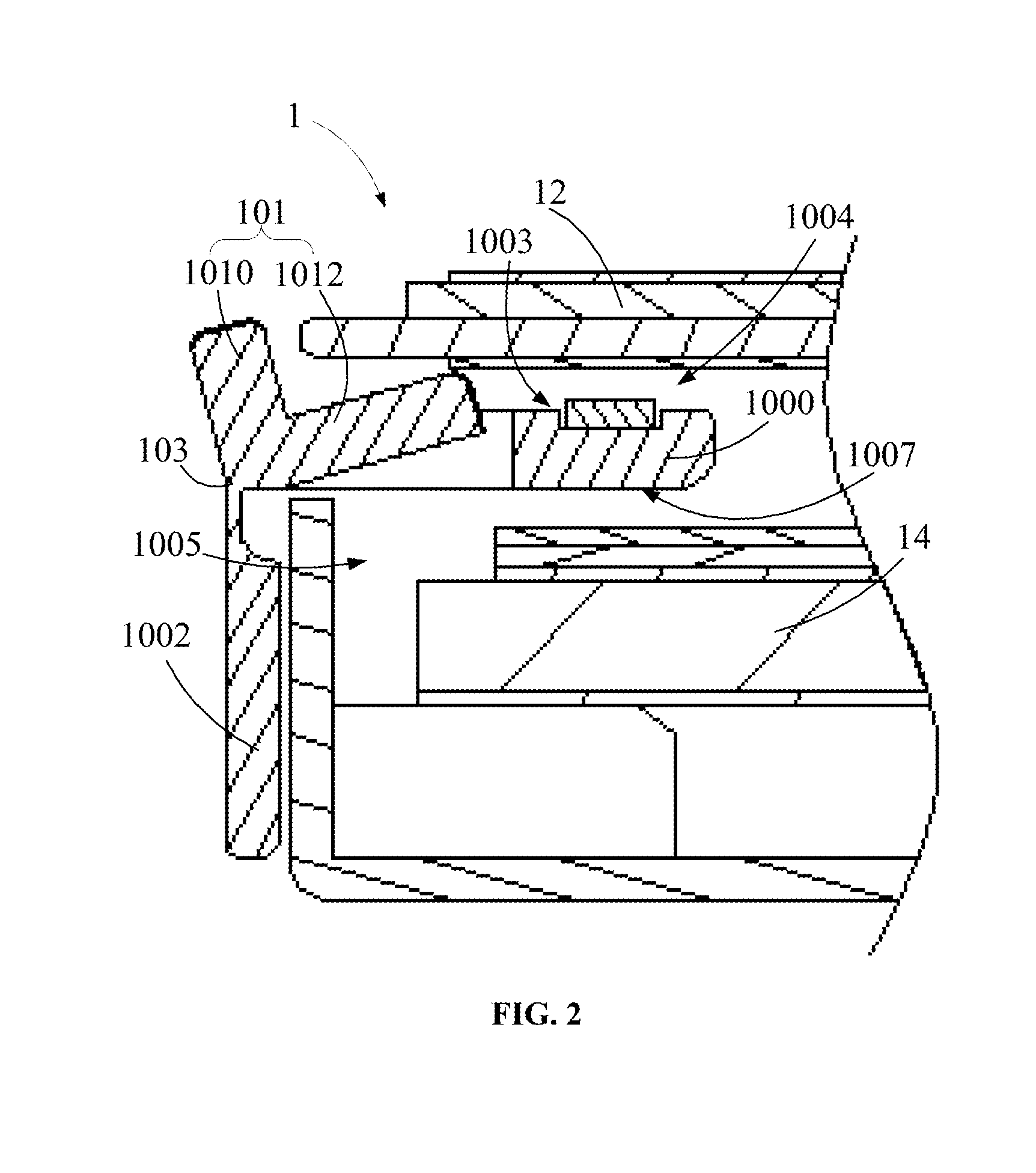
[0029]Referring to FIGS. 1 and 2, the present invention provides a display device 1. The display device 1 includes a frame 10, a display panel 12 held in the frame 10, and a backlight module 14. The frame 10 includes a number of side frames 100 and at least one rotating part 101. The side frames 100 are connected end to end to form an enclosed frame for accommodating the display panel 12. The side frame 100 defines at least one cutout 102 extending along a longitudinal direction of the side frame 100. The rotating part 101 is received in the cutout 102 and is rotatably connected to the side frame 100 via a rotating axis 103 extending along the longitudinal direction of the side frame 100. The display panel 12 is assembled in the enclosed frame via the rotating part 101. In this embodiment, the frame 10 includes four side frames 100. The four side frames are connected end to end to form a rectangular receiving frame. The display panel may be, but is not limited to, a liquid crystal d...

second embodiment

[0035]Referring to FIGS. 4 and 5, the present invention provides a display device 2. A structure of the display device 2 is similar to the structure of the display device 1. A difference between the display device 2 and the display device 1 is the cutout 202 only includes a third part 2020 defined in the first side wall 2001. The rotating part 201 includes an elongated circular roller 2010 and a rotating axis 203 passing through the roller 2010 along a rotational symmetry axis of the roller 2010. Two opposite ends of the rotating axis 203 along a longitudinal direction of the rotating axis 203 are correspondingly connected to two opposite end surfaces of the cutout 202 to assembly the roller 2010 in the cutout 202, and make the roller 2010 to rotate around the rotating axis 203 extending along the longitudinal direction of the side frame 200. The diameter of the roller 2010 is the same as a height of a portion of the second side wall 2001 extending from the holding board 2000.

[0036]...


PUM


Abstract

The present invention discloses a frame for holding a display panel. The frame includes a number of side frames and at least one rotating part. The side frames are connected end to end to form an enclosed frame for accommodating the display panel. The side frame defines at least one cutout extending along a longitudinal direction of the side frame. The rotating part is received in the cutout and is rotatably connected to the side frame via a rotating axis extending along the longitudinal direction of the side frame. The display panel is assembled in the enclosed frame via the rotating part. The present invention further provides a display device having the frame.

Description

TECHNICAL FIELD OF THE INVENTION[0001]The invention relates to frames and display devices using the frames, and particularly, to a frame used to hold and position a display panel.BACKGROUND OF THE INVENTION[0002]A frame used in a current display device for holding a display panel usually reserves a gap between a peripheral wall of the frame and a periphery of the display panel. However, a size of the reserved gap is difficult to determine. If the reserved gap is too large, the display panel assembled in the frame is easy to move and the frame fails to satisfy a slim design demands. If the reserved gap is too small, the display panel is difficult to be assembled in the frame.[0003]Therefore, a frame can solve the above-mentioned problem needs to be provided.SUMMARY OF THE INVENTION[0004]To solve the above-mentioned problem, an embodiment of the present invention provides a frame for holding a display panel. The frame includes a number of side frames and at least one rotating part. Th...

Claims


Application Information

Patent Timeline
IPC IPC(8): H05K5/02A47B81/06H05K5/00
CPCH05K5/0217A47B81/06H05K5/0017G02F1/133308G02F2001/133317G02F2001/133322H04N5/64G06F1/1601G02F1/133322G02F1/133317
Inventor HSIAO, YUCHUNHUANG, CHONG
Owner SHENZHEN CHINA STAR OPTOELECTRONICS TECH CO LTD
Features
  • R&D
  • Intellectual Property
  • Life Sciences
  • Materials
  • Tech Scout
  • Unparalleled Data Quality
  • Higher Quality Content
  • 60% Fewer Hallucinations
Learn More