Multiuser-Capable Test Environment for a Plurality of Test Objects

a test environment and multi-user technology, applied in the field of multi-user-capable test environment for testing test objects, to achieve the effect of enhancing the economic utility of the test environmen

Active Publication Date: 2016-03-10
AIRBUS DEFENCE & SPACE
View PDF6 Cites 1 Cited by
  • Summary
  • Abstract
  • Description
  • Claims
  • Application Information

AI Technical Summary

Benefits of technology

[0005]Making possible enhanced economic utility of a test environment and selective access by a plurality of test case implementation units to one or a plurality of test objects may be considered an object of the invention.
[0008]The coupling between one test case implementation unit and one test object is reversible, that is, after the implementation of a test case of the first test case implementation unit a test object may be decoupled from the first test case implementation unit and may be coupled to the second test case implementation unit for implementing another test case. In other words, this prevents a rigid coupling between a test object and a test case implementation unit and makes it possible to implement successively different and multiple test cases of different test case implementation units. The test case implementation units may also be spatially separated from the test object. This means that a test case is acted upon by remote access to the test object. The test case implementation units may also be spatially distributed such that they are in different time zones so that the most economic possible use is made of the test object and test environment and of the time available for implementing test cases.
[0020]The connection unit makes it possible to implement or switch a connection element of the input interface to a connection element or a plurality of connection elements of the output interface so that the corresponding test case implementation unit is coupled to a test object or to a plurality of test objects via the connection unit.
[0023]In one embodiment, the coupling between a test case implementation unit and a test object may occur both ways, specifically, via the connection unit and via the connection bus. This may in particular increase the reliability of the test environment or the reliability of the signal coupling between a test case implementation unit and a test object.
[0034]The test environment, as described above and in the following, facilitates a modular structure and selective linking of test case implementation units, test objects, and simulation hardware units, so that in particular it is possible for a plurality of operators or testers to access one or a plurality of test objects, wherein at the same time the use of the test environment is made possible for a number of different test objects without the entire test environment having to be adapted to one test object. The connection unit has the task of producing a coupling between the different test objects and the test case implementation units.

Problems solved by technology

If the measured data deviate from the pre-specified and expected output data, this may indicate a malfunction of the test object.

Method used


Image

  • Multiuser-Capable Test Environment for a Plurality of Test Objects
  • Multiuser-Capable Test Environment for a Plurality of Test Objects

Examples


Embodiment Construction

[0040]The representations in the figures are schematic and are not true to scale. When the same reference numbers are used in the following description of the figures, they refer to the same or similar elements.

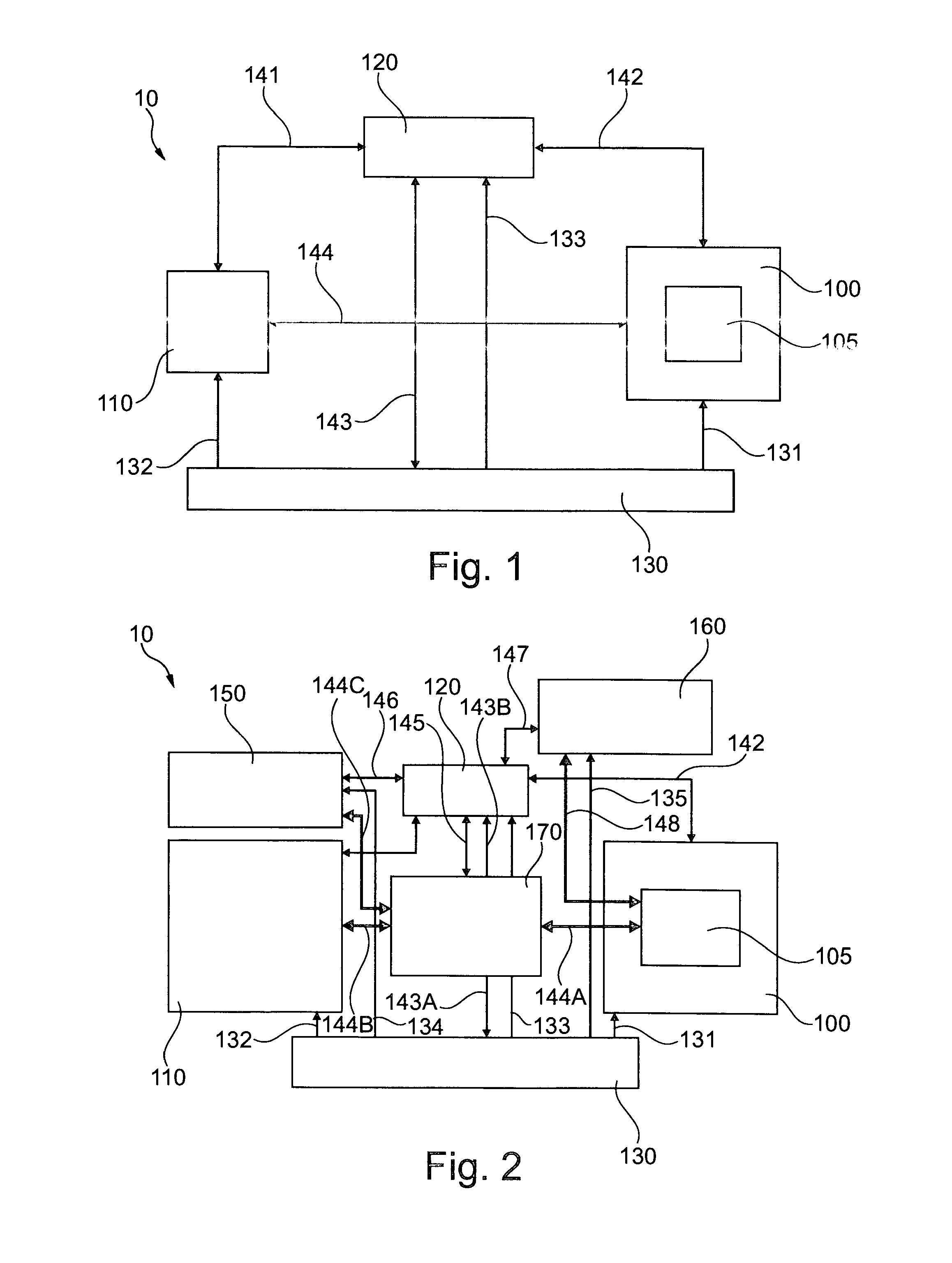
[0041]FIG. 1 depicts a test environment 10 having a test case implementation unit 110 and a test object 105 that is arranged in a test object receiving device 100. A control device 120 is provided for controlling the test case implementation unit 110 and for controlling the test object receiving device 100 and the test object 105. Likewise, the control device 120 controls an energy supply unit 130 that supplies the test case implementation unit 110, the test object receiving device 100, the test object 105 and the control device 120 with energy for implementing a test.

[0042]The unidirectional arrows 131, 132, 133 provide a schematic representation of the energy supply for the test object receiving device 100, test case implementation unit 110, and control device 120. The dire...


PUM


Abstract

The present invention relates to an arrangement for providing a test environment for testing test objects. The arrangement includes a first test case implementation unit and a second test case implementation unit, as well as a first test object and a second test object. In one embodiment, the test environment is configured such that at least the first test case implementation unit is coupled to at least one of the first test object and the second test object for implementing a test case.

Description

FIELD OF THE INVENTION[0001]The invention relates to a test environment for testing test objects that may be, for instance, a technical system, a subsystem of a technical system, or another technical component, and in particular a safety-related component, such as, e.g., a component of an aircraft or of an aircraft computer.BACKGROUND OF THE INVENTION[0002]After technical components are developed and prior to their use, they may need to be tested to determine how they behave in various situations. Such a test may comprise a plurality of test cases, wherein each test case has a set of input data and a set of expected output data. Simply put, the test object is acted upon with the input data and the reaction or behavior of the test object relative to these input data is measured. The data measured in this way are then compared to the expected output data associated with this test case. Agreement between the measured data and the expected output data indicates correct functioning of th...

Claims


Application Information

Patent Timeline
Patent Type & Authority Applications(United States)
IPC IPC(8): G01R31/319G06F11/30
CPCG01R31/31903G06F11/3041G01R31/31907G01R31/2834G06F11/3664G06F11/273
Inventor WAGER, PHILIPPSCHUMACHER, BERND
Owner AIRBUS DEFENCE & SPACE
Why Eureka
Try Eureka