
Heat dissipating device having turbine ventilator and LED lamp comprising the same

a technology of heat dissipation device and led lamp, which is applied in the direction of semiconductor devices for light sources, semiconductor/solid-state device details, lighting and heating apparatus, etc., can solve the problems of consuming extra electricity from the dissipating fan, reducing the life of led lamps, and high maintenance costs, so as to improve the economic and practical utility. , the effect of dissipating the heat of the led lamp

Inactive Publication Date: 2011-03-22
EDISON-OPTO
View PDF6 Cites 1 Cited by
  • Summary
  • Abstract
  • Description
  • Claims
  • Application Information

AI Technical Summary

Benefits of technology

"The present invention provides a heat dissipating device with a turbine ventilator for LED lamps. The device includes a heat dissipater with a plurality of heat dissipating fins arranged at intervals, and a turbine ventilator connected to the heat dissipater. The turbine ventilator has a central axis that parallels the heat dissipating passage, and it is designed to make no noise during operation. The LED lamp comprises a substrate with LEDs and a heat dissipating device. The technical effects of the invention include improved economical and practical utility, as well as improved user experience due to the absence of noise."

Problems solved by technology

If the heat cannot be dissipated sufficiently, it will reduce the lifetime of LEDs and result in higher maintenances cost.
However, the additional heat dissipating fan consumes extra electricity, which contradicts the purposes of replacing traditional lamp devices for power saving and environment protecting.
Some heat dissipating fans in operation will make loud noise.
It not only increases power consumption but also makes user uncomfortable.

Method used


Image

  • Heat dissipating device having turbine ventilator and LED lamp comprising the same
  • Heat dissipating device having turbine ventilator and LED lamp comprising the same
  • Heat dissipating device having turbine ventilator and LED lamp comprising the same

Examples


Embodiment Construction

[0019]In cooperation with attached drawings, the technical contents and detailed description of the invention are described thereinafter according to a number of preferable embodiments, being not used to limit its executing scope. Any equivalent variation and modification made according to appended claims is all covered by the claims claimed by the present invention.

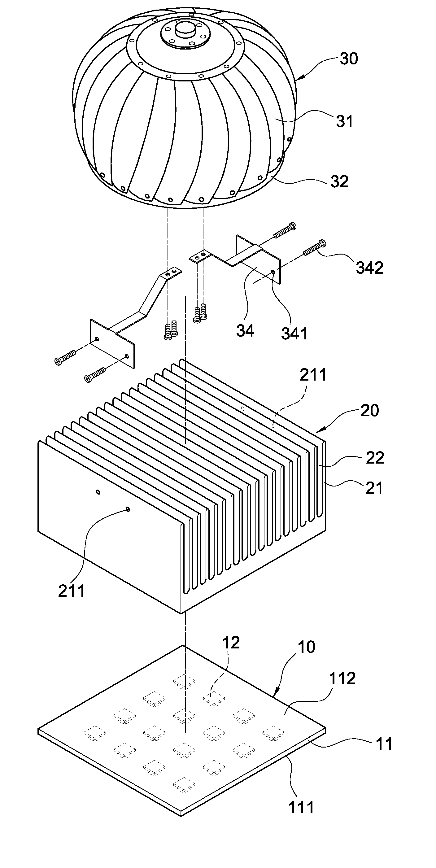
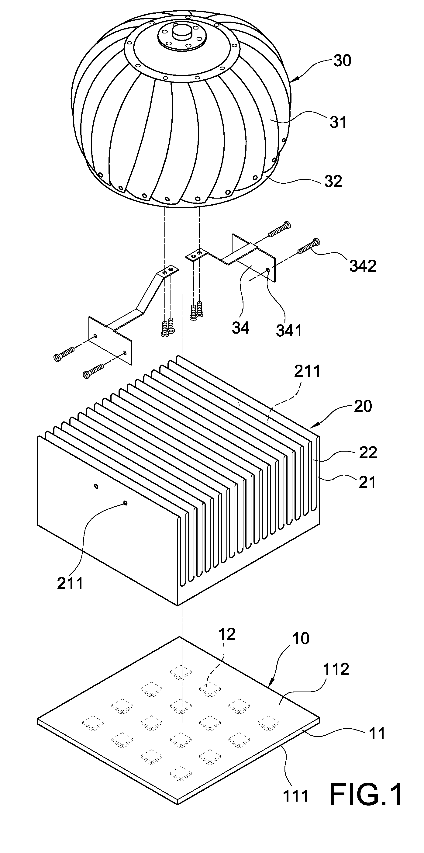
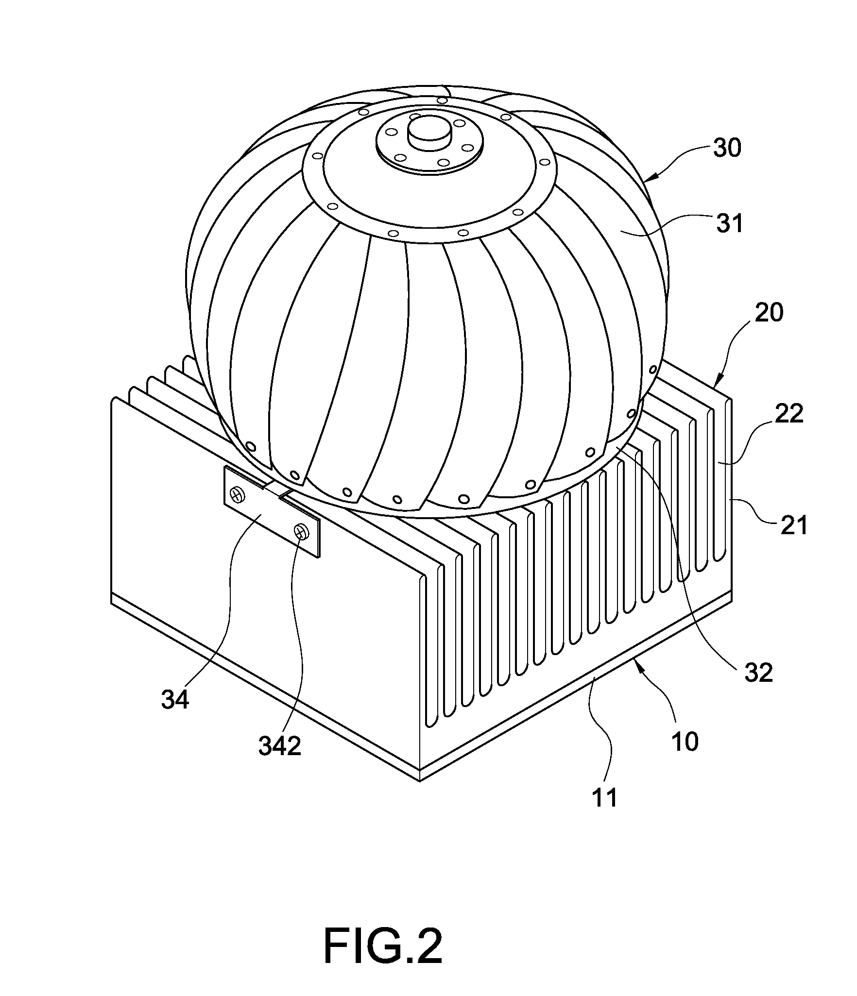
[0020]With refer to FIG. 1 and FIG. 2, an exploded perspective view of the present invention and a schematic view showing the present invention are respectively shown. The present invention provides a heat dissipating device having a turbine ventilator. The heat dissipating device comprises a heat dissipater 20 and a turbine ventilator 30. The heat dissipater 20 includes a plurality of heat dissipating fins 21 which arranged at interval, where a heat dissipating passage 22 is defined between two adjacent heat dissipating fins 21. The turbine ventilator 30 is composed of a plurality of bent fins 31 which are installed on ...


PUM


Abstract

A heat dissipating device includes a heat dissipater and a turbine ventilator. The heat dissipater includes a plurality of heat dissipating fins arranged at interval, wherein a heat dissipating passage is defined between two adjacent heat dissipating fins. The turbine ventilator is connected to one side of the heat dissipater, and the turbine ventilator has a central axis and the axial line of the central axis is in parallel to the heat dissipating passage. An LED lighting module can be attached to one side of the heat dissipater of the heat dissipating device. Therefore, the heat dissipating device dissipates heat of the LED lighting module without consuming additional electrical power.

Description

BACKGROUND OF THE INVENTION[0001]1. Field of the Invention[0002]The present invention generally relates to a heat dissipating device, in particular to a heat dissipating device for an LED lamp.[0003]2. Description of Prior Art[0004]Generally speaking, as light emitting diodes (LEDs) come with the features of low power consumption, power saving, long service time, small size and quick response etc., LED lamps gradually substitute traditional light bulbs and have been extensively used in various light emitting devices.[0005]A plurality of LEDs are usually used together to comprise an LED module for increasing the lighting area and luminance. As the number of LED used increased, the heat generated from the operating LED module also increased. If the heat cannot be dissipated sufficiently, it will reduce the lifetime of LEDs and result in higher maintenances cost. Hence, the generated heat from LEDs usually requires a heat dissipating device to thermally manage the temperature for maint...

Claims


Application Information

Patent Timeline
Patent Type & Authority Patents(United States)
IPC IPC(8): F21V29/02H01K1/58
CPCF21V29/02F21V29/763F21W2131/103F21Y2101/02H01L2924/0002H01L23/467H01L2924/00F21Y2115/10F21V29/67
Inventor SUN, TSUNG-TING
Owner EDISON-OPTO
Learn More