Plant holder and transplantation device

a technology for transplanting devices and plant holders, which is applied in the field of plant holders and transplantation devices, can solve the problems of reducing space efficiency and deteriorating production efficiency, and achieve the effects of increasing the diameter of the holding hole, facilitating transplantation, and increasing the diameter of the fitting portion

Inactive Publication Date: 2016-03-17
TSUBAKIMOTO CHAIN CO
View PDF12 Cites 3 Cited by
  • Summary
  • Abstract
  • Description
  • Claims
  • Application Information

AI Technical Summary

Benefits of technology

[0025]According to the plant holder according to claim 1, it becomes possible to increase the diameter of the fitting portion and increase the diameter of the holding hole of the cultivation panel, and it is possible to cause the root of the plant stock to pass through the holding hole downwardly and extend downward without damaging the root of the plant stock, and hence it is possible to easily perform transplantation without adding a complicated facility in an automated cultivation facility.
[0026]In addition, the outer diameter of the flange portion is formed larger than the outer diameter of the placement portion, whereby it becomes possible to lift the flange portion from below only by inserting the holding arms having the distance between the holding arms smaller than the outer diameter of the flange portion from the side of the placement portion, and it is not necessary to provide a movable mechanism at a tip when handling of the plant holder is automated.
[0027]With this, it is possible to improve workability when the transplantation and the harvest are automated without damaging the plant stock by contact with the plant stock with a simple configuration.
[0028]Further, the placement portion and the flange portion do not hinder the handli

Problems solved by technology

In the hydroponic cultivation facility, for example, in the case where a plant that grows widely in a horizontal direction is held by a holding panel and is cultivated, space efficiency

Method used


Image

  • Plant holder and transplantation device
  • Plant holder and transplantation device
  • Plant holder and transplantation device

Examples


embodiment

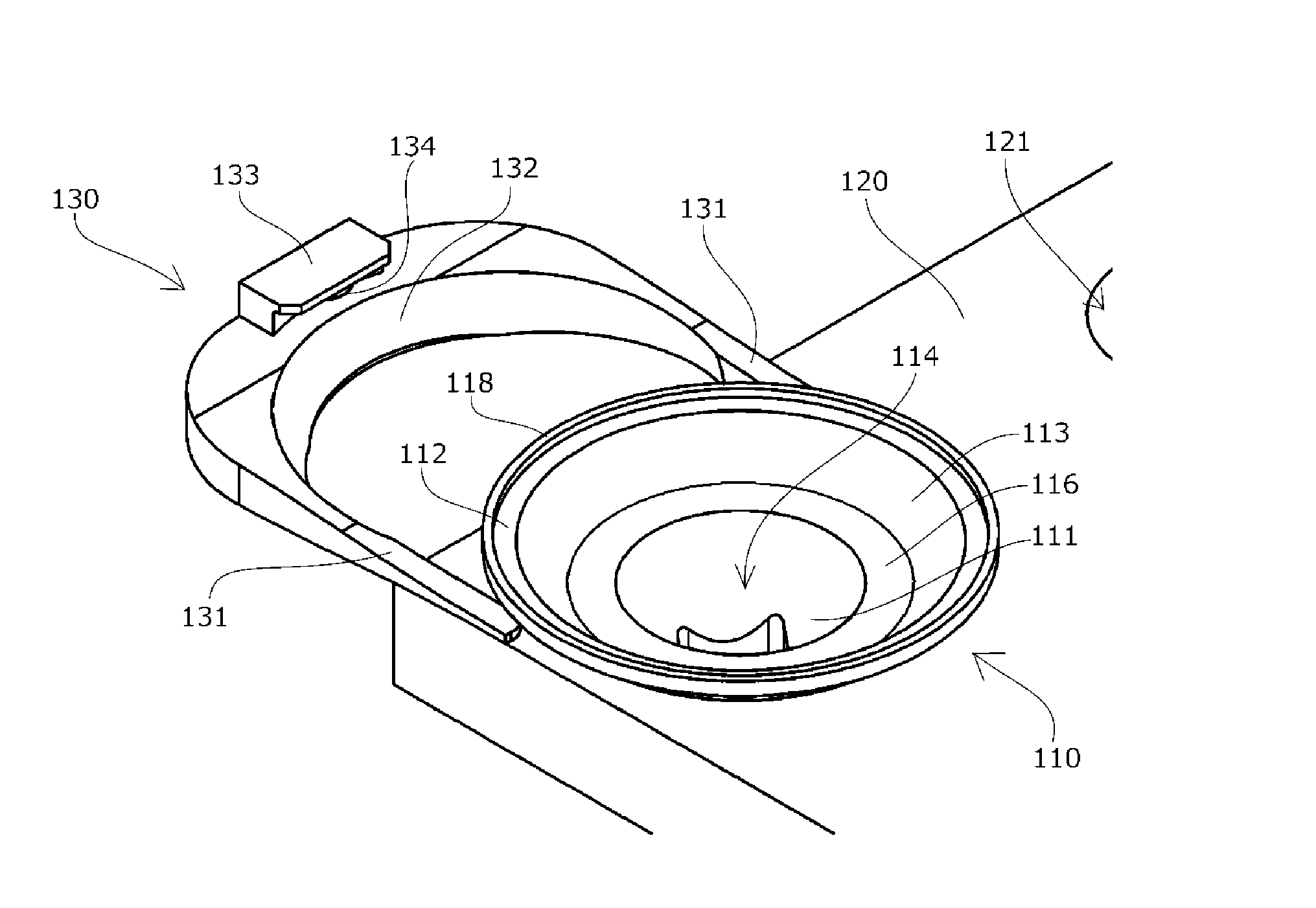
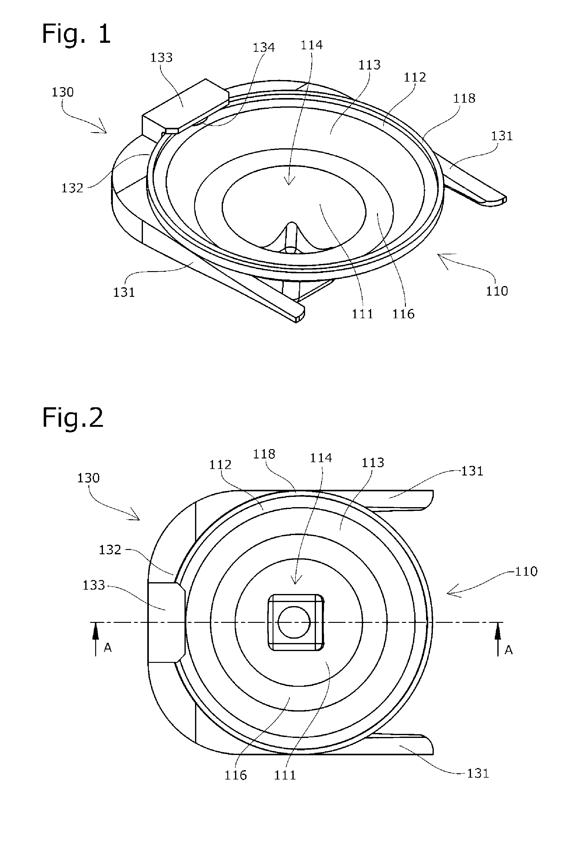
[0076]An embodiment of each of the plant holder and the transplantation device of the present invention will be described based on FIGS. 1 to 7.

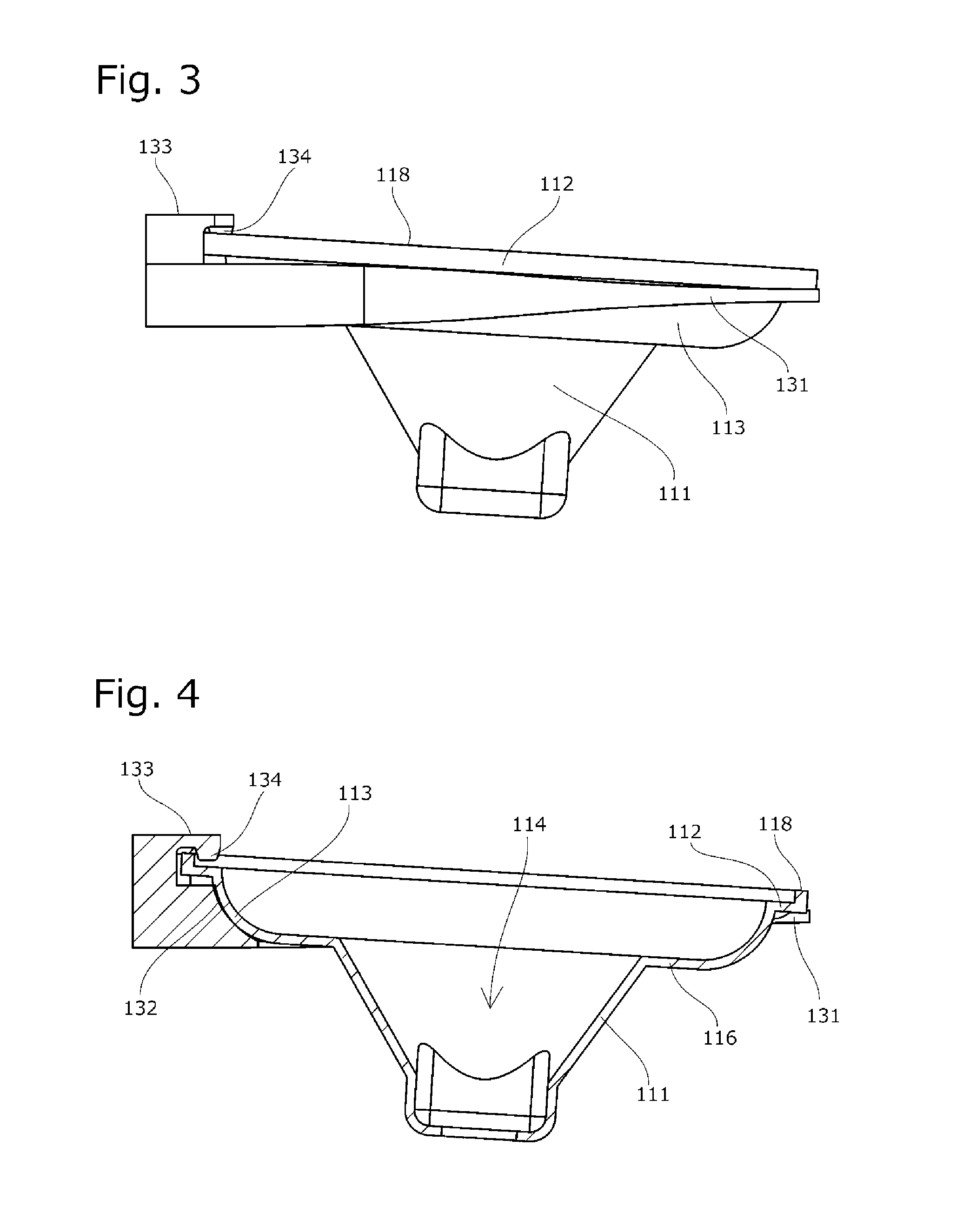
[0077]A plant holder 110 as the embodiment of the present invention is integrally formed of a resin or the like so as to have a substantially uniform thickness, and has a flange portion 112, a placement portion 113, and a fitting portion 111 from above.

[0078]An inner surface of the fitting portion 111 has a plant stock support hole 114 formed into a tapered shape, and its outer periphery is formed into a tapered shape which can be inserted into a holding hole 121 of a cultivation panel 120 from above.

[0079]In the present embodiment, the lowermost portion of the fitting portion 111 is formed into a shape of a square tube having a large thickness in order to maintain strength.

[0080]The outer diameter of the placement portion 113 is formed larger than the outer diameter of the fitting portion 111, and the placement portion 113 has a flat surfac...


PUM


Abstract

There is provided a plant holder capable of, with a simple configuration, causing a root of a plant stock to pass through a holding hole downwardly without damaging the root of the plant stock, preventing a leaf from drooping downward and being damaged, and improving workability when transplantation and harvest are automated without damaging the plant stock by contact with the plant stock.
A plant holder 110 includes a fitting portion 111 and having a plant stock support hole 114 in an inner surface, a placement portion 113 which is provided above the fitting portion 111, and a flange portion 112 which is provided above the placement portion 113. The outer diameter of the placement portion 113 is formed smaller than the outer diameter of the flange portion 112, and larger than the outer diameter of the holding hole 121.

Description

TECHNICAL FIELD[0001]The present invention relates to a plant holder which has an outer peripheral portion, at least part of which is fitted in a holding hole of a cultivation panel, and a plant stock support hole supporting a plant stock directly or indirectly, and which is held by the cultivation panel, and a transplantation device which holds and moves the plant holder, and relates to a plant holder and a transplantation device suitable for automating transplantation of a plant stock corresponding to its growth and harvest of the grown plant stock in, e.g., a hydroponic cultivation facility such as in a plant factory.BACKGROUND ART[0002]Conventionally, in a plant factory or the like, a hydroponic cultivation facility in which a plant stock is held by a holding member such as, e.g., a cultivation panel having a plurality of holding holes, and a root of the plant stock that grows downward through the holding holes of the cultivation panel is soaked in a cultivation liquid or the li...

Claims


Application Information

Patent Timeline
IPC IPC(8): A01G31/02
CPCA01G31/02A01G9/083A01G9/086A01G9/0299
Inventor KOUNO, KOUJIHIRAI, TATSUYAOKAZAKI, YUOHARA, HITOSHI
Owner TSUBAKIMOTO CHAIN CO
Why Eureka
Try Eureka