Al technical title is built by PatSnap Al team. It summarizes the technical point description of the patent document.
a fitting and adjustable technology, applied in the field of customizing fitted equipment, can solve the problems of skin irritation, non-removable cast, non-breathable and non-waterproof type of cast, etc., and achieve the effect of easy removal from the user
Inactive Publication Date: 2016-03-17
HALL DIANA
View PDF3 Cites 16 Cited by
Summary
Abstract
Description
Claims
Application Information
AI Technical Summary
This helps you quickly interpret patents by identifying the three key elements:
Problems solved by technology
Method used
Benefits of technology
[0008]When the device is ready for use, the one or more sidewall sections can be placed around the target area of the user so that the one or more sidewall sections meet at the one or more longitudinal seams, thereby forming an enclosed sidewall around the target area. The connectors or clips can then be inserted through the receiver openings and secured to holder the connector receivers together. Once all connector receivers are secured, the device forms a rigid or supporting device around the target area. The device can then be easily removed from the user by removing the connectors or clips and separating the sidewall section(s).
Problems solved by technology
While this style of casts is generally effective at immobilizing the targeted body portion and is generally inexpensive to produce, it has several limitations.
One main limitation is that the cast is not removable.
Another limitation is that this type of cast is non-breathable and non-waterproof.
This can lead to skin irritation and other issues as well as damage to the cast when the patient encounters wet conditions.
Method used
Image
Click on the blue label to locate the original text in one second.
Reading with bidirectional positioning of images and text.
Examples
Embodiment Construction
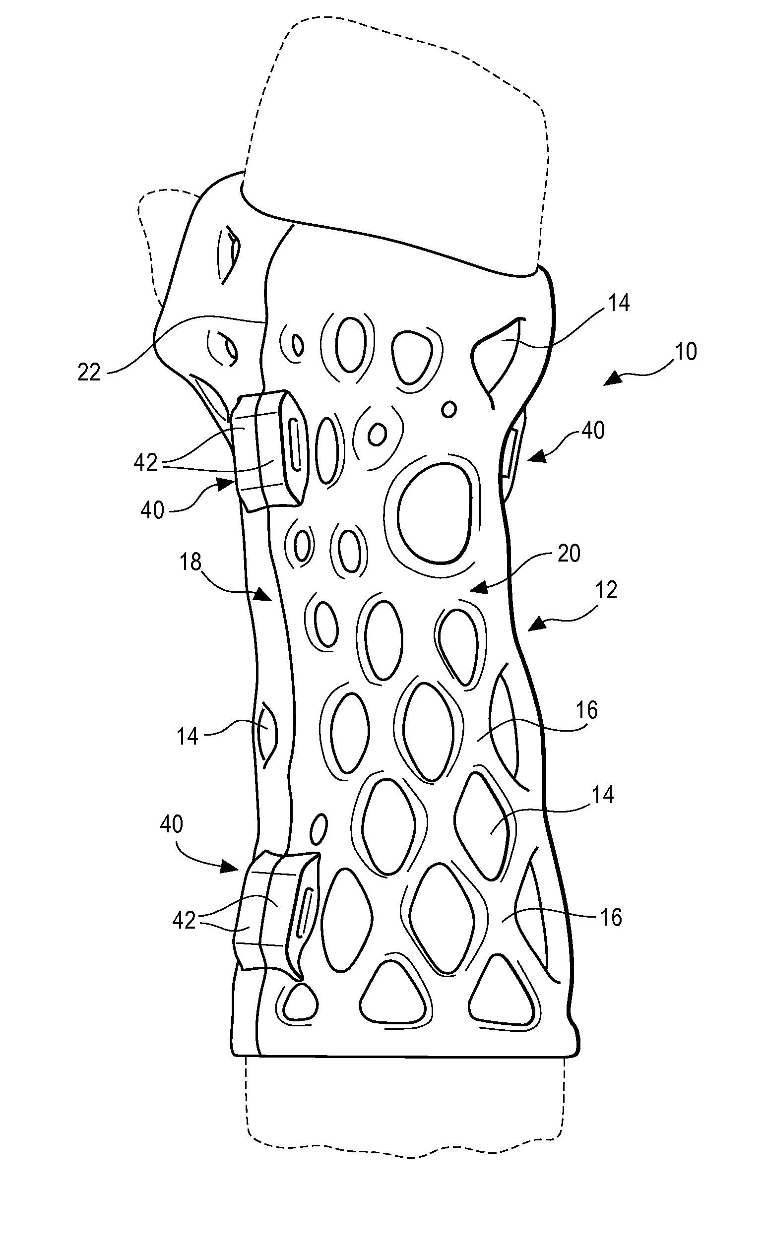
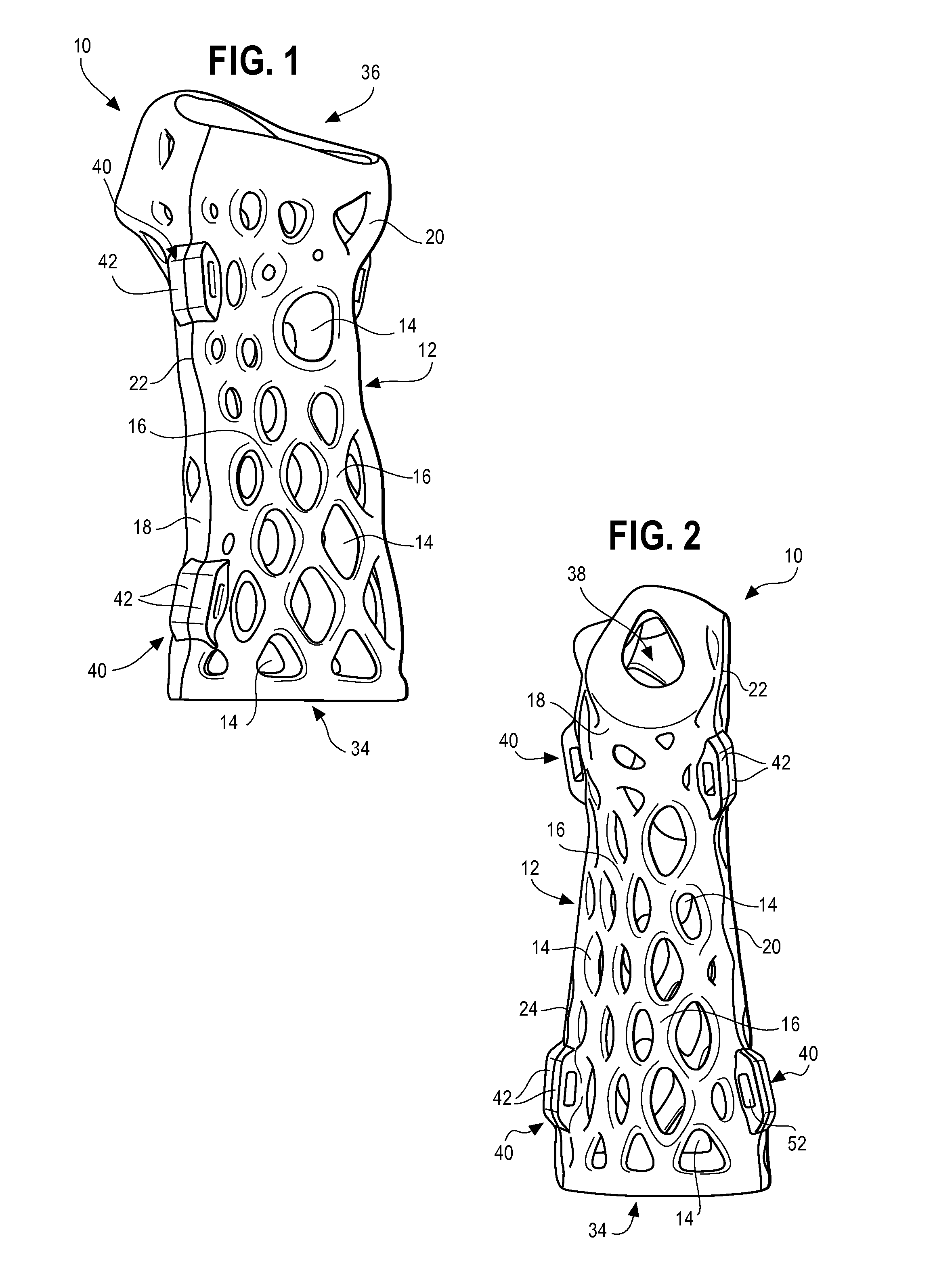
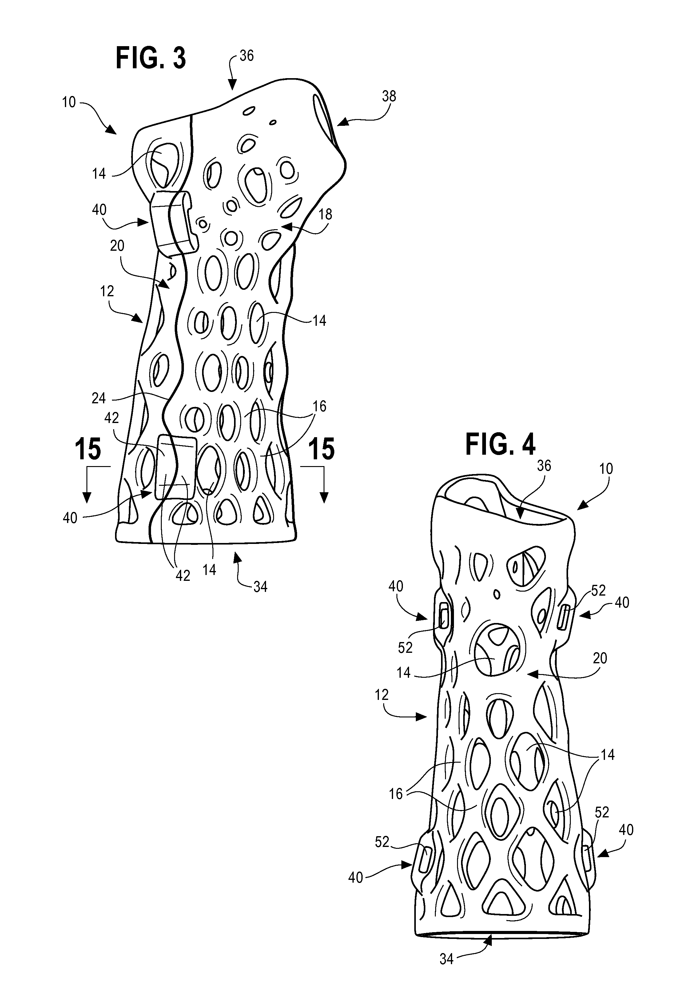
[0027]The invention will now be described with reference to the drawing figures, in which like reference numerals refer to like parts throughout. For purposes of clarity in illustrating the characteristics of the present invention, proportional relationships of the elements have not necessarily been maintained in the drawing figures.
[0028]The following detailed description of the invention references specific embodiments in which the invention can be practiced. The embodiments are intended to describe aspects of the invention in sufficient detail to enable those skilled in the art to practice the invention. Other embodiments can be utilized and changes can be made without departing from the scope of the present invention. The present invention is defined by the appended claims and the description is, therefore, not to be taken in a limiting sense and shall not limit the scope of equivalents to which such claims are entitled.
[0029]The present invention is directed toward a fitted dev...
PUM
Abstract
A customizable fitted device for immobilizing injuries and a method for constructing the fitted device is provided. The fitted device can be used to stabilize an al 1, wrist, hand, leg, knee, ankle, foot or other body parts through custom formation. The device can be formed by a sidewall having one or more sidewall sections that can be secured together using retaining clips positioned within retaining clip slots on the device. The device can further include one or more openings defined in the sidewall of each device section while maintaining rigidity in the sidewall. The device can be constructed by of creating a 3D image scan of the particular body part in which the device will be applied, creating a design of the device to precisely match the contours of the 3D image scan, and using a 3D printer to construct the device according to the design.
Description
CROSS-REFERENCE TO RELATED APPLICATIONS[0001]This Application claims priority to U.S. Provisional Patent Application Ser. No. 62 / 050,067, filed on Sep. 12, 2014, to Diana Hall, entitled “Amphibian Skin Custom-fit Exoskeleton Support Devices,” currently pending, the entire disclosure of which is incorporated herein by reference, and U.S. Provisional Patent Application Ser. No. 62 / 162,743, filed on May 17, 2015, to Diana Hall, entitled “Amphibian Skin 3D Printed Clips and Cable Tie Slots,” currently pending, the entire disclosure of which is incorporated herein by reference.BACKGROUND OF THE INVENTION[0002]The present invention relates to devices, such as casts, splints, braces, and similar devices for immobilizing and stabilizing various portions of a user's body, including arms, elbows, wrists, hands, legs, knees, ankles, feet and other structures. Such devices are also used in veterinary applications and other various alternative uses.[0003]When a user's body portion needs stabiliz...
Claims
Application Information
Patent Timeline
Application Date:The date an application was filed.
Publication Date:The date a patent or application was officially published.
First Publication Date:The earliest publication date of a patent with the same application number.
Issue Date:Publication date of the patent grant document.
PCT Entry Date:The Entry date of PCT National Phase.
Estimated Expiry Date:The statutory expiry date of a patent right according to the Patent Law, and it is the longest term of protection that the patent right can achieve without the termination of the patent right due to other reasons(Term extension factor has been taken into account ).
Invalid Date:Actual expiry date is based on effective date or publication date of legal transaction data of invalid patent.
Patent Type & Authority Applications(United States)