Braided composite spar

a composite material and spar technology, applied in the direction of spars/stringers, air-flow influencers, applications, etc., can solve the problems of difficult manufacturing and construction of composite materials, difficult to adequately tailor the structural behaviour of composite beams, and wing tip devices that are overengineered, etc., to achieve the effect of reducing the height of the spar or preform

Active Publication Date: 2016-03-17
AIRBUS OPERATIONS LTD
View PDF0 Cites 7 Cited by
  • Summary
  • Abstract
  • Description
  • Claims
  • Application Information

AI Technical Summary

Benefits of technology

[0013]There are two benefits in increasing the fibre pitch (by increasing the ratios S / ω1 and S / ω2) in the direction of inward taper and reducing circumference. Firstly it causes a reduction in fibre angle which goes beyond that which would be created by winding the fibres onto the mandrel at a constant speed and pitch (as in the prior art). This enables the structural properties of the spar or preform to be tailored as required—for instance providing higher bending stiffness at the tip than at the root. For example the first and second sets of fibres may have a fibre angle which changes by more than 10° or 15° in the tapered portion. At the same time it counteracts the tendency of the tapering mandrel to gradually increase the areal weight and thickness of each ply. Thus each ply may have an areal weight or thickness which does not change in the tapered portion, or at least does not change by more than 10% or 5% within the tapered portion. Typically each ply also has an areal weight or thickness which does not change by more than 10% or 5% over the entire length of the spar or preform. Providing a relatively constant areal weight and / or thickness (despite the tapered shape of the spar or preform) enables the spar or preform to be modelled and analysed more easily by computer-aided design.
[0017]In a conventional braided spar of varying circumference, the fibre angle, thickness and areal weight vary as the circumference varies. The special shape of the braided spar or preform of the fourth aspect of the invention has a particular benefit since it enables the height of the spar or preform to be reduced without a large accompanying change in circumference.

Problems solved by technology

In the large civil aircraft aviation industry the growth in size of wing tip devices over the years as a result of drive to increase wing efficiency through reduction of drag has lead to technical challenges related to the load transfer and efficient joint technology between the wing tip device and wing.
However, the wing tip device tends to be over-engineered, particularly at the attachment point, in order to guarantee the mechanical properties required for the use of such fastening means because current manufacturing methodologies make it difficult to adequately tailor the structural behaviour of the composite beam.
It remains difficult to manufacture and construct using composite materials the complex spar geometry that enables a winglet to be attached to a main wing element.
The use of conventional methods such as an assembly of multiple parts to form the spar are difficult due to the lack of access in the geometry available for tooling and assembly, and also inefficient as a result of requiring an increased number of parts, thus increasing cost and weight of the final component, or resulting in a compromise of the structural design to meet the manufacturing constraints.

Method used


Image

  • Braided composite spar
  • Braided composite spar
  • Braided composite spar

Examples


Embodiment Construction

)

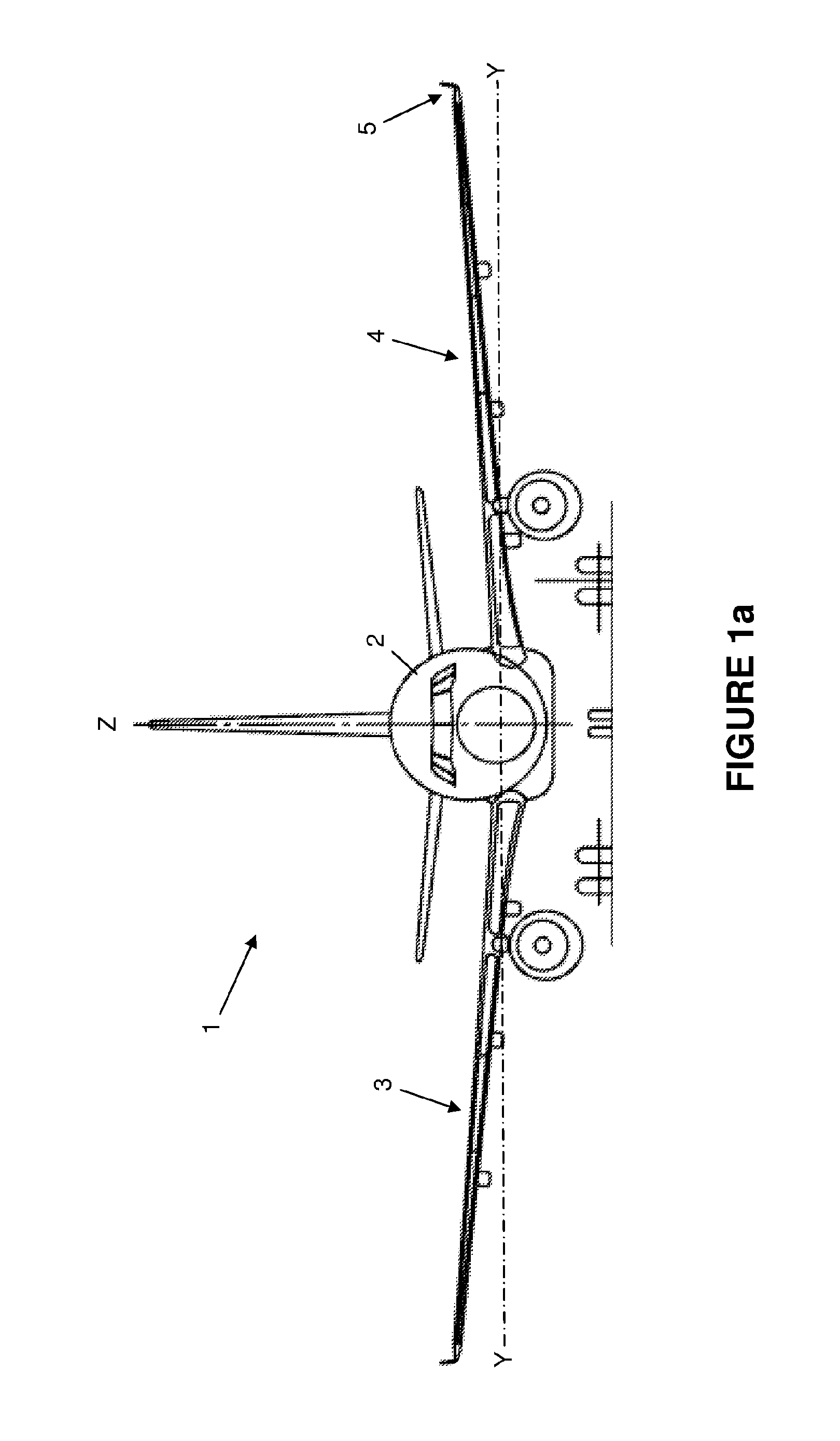
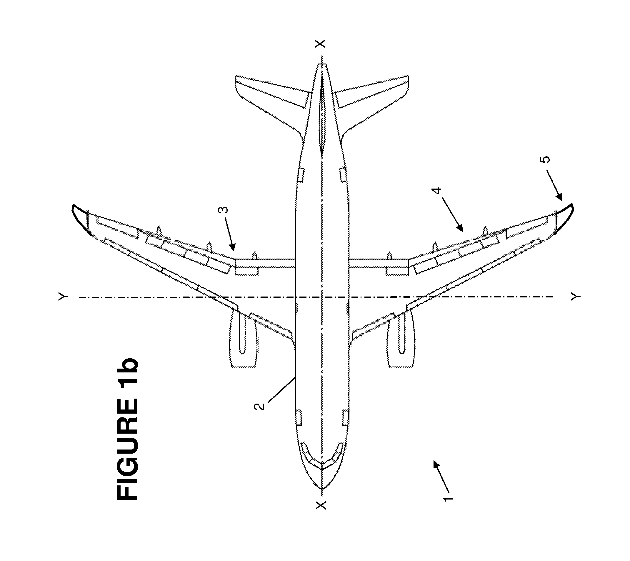
[0053]FIGS. 1a and 1b show an aircraft 1 with a fuselage 2 carrying a pair of wings 3,4.

[0054]The aircraft has a horizontal fore / aft axis (labelled X) and a horizontal inboard / outboard axis (labelled Y) normal to the fore / aft axis. Each wing has a winglet and the winglet 5 at the tip of the port wing 4 is shown in FIG. 1c. The port wing 4 comprises a main wing element 6 with a tip 7, and a winglet 5 attached to the tip. The main wing element 6 has front and rear spars running along its full span from a root near the fuselage 2 to its tip 7. Only the webs 8,9 of these spars are shown in FIG. 1 but they also have spar caps which could point in (towards the other spar) or out. A fuel tank is housed in the main wing element 6 between the spar webs 8,9.

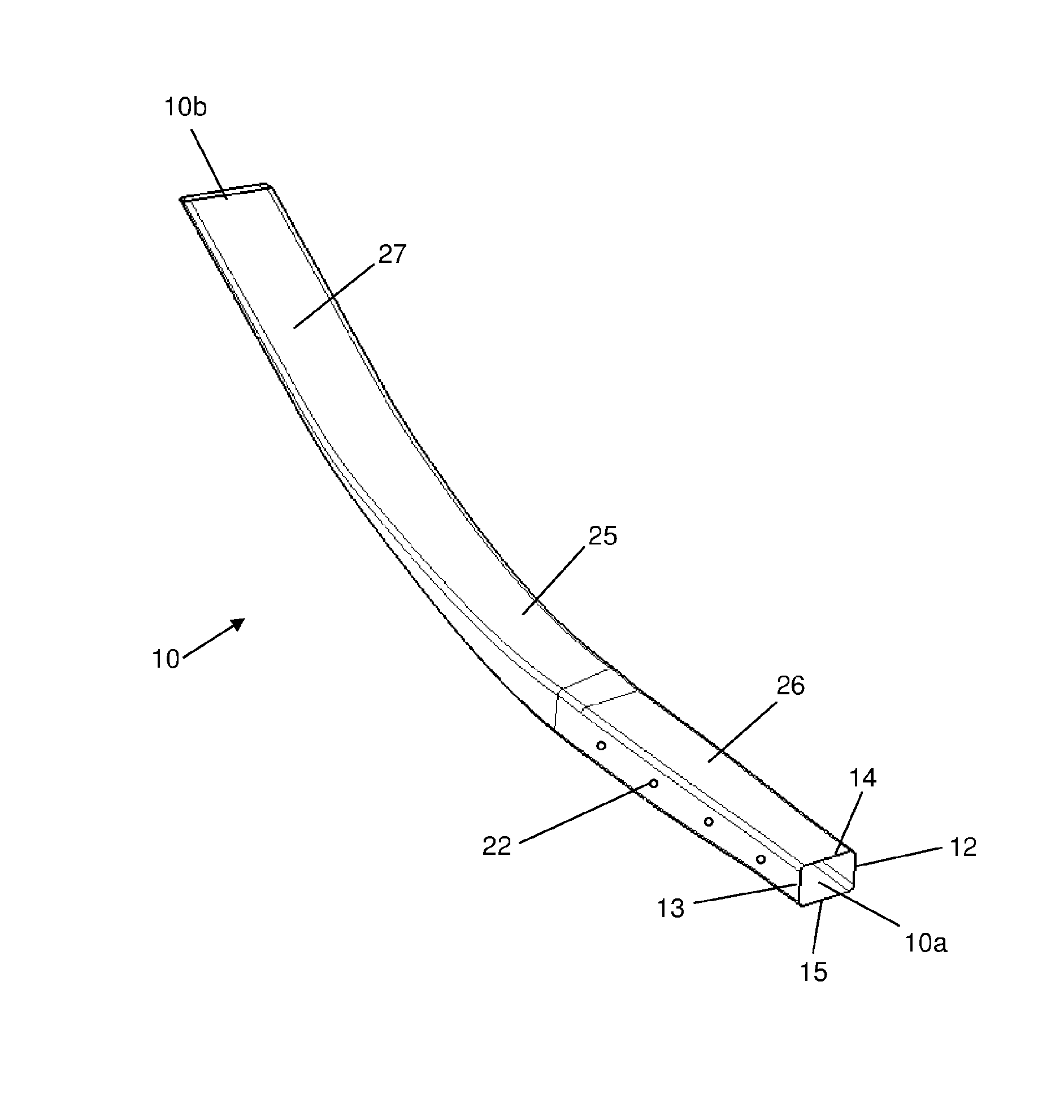
[0055]The winglet 5 has a main (rear) spar 10 and a front spar 11. The main spar 10 extends from a root 10a to a tip 10b which is short of a tip 5a of the winglet 5 so it does not run along the full span of the winglet. The front spar 11 ...


PUM

PropertyMeasurementUnit
fibre angleaaaaaaaaaa
thicknessaaaaaaaaaa

Abstract

A braided composite spar or preform for a braided composite spar with a plurality of tubular plies of braided fibres. Each ply has a first set of fibres which wind in a clockwise direction in a first series of turns with a pitch between each adjacent pair of turns, and a second set of fibres which wind in an anti-clockwise direction in a second series of turns with a pitch between each adjacent pair of turns. The first and second sets of fibres in each ply are intertwined to form a braided structure. The spar or preform extends lengthwise from a root to a tip and has a tapered portion which tapers inwardly towards the tip. Each ply has a circumference in the tapered portion which reduces as it tapers inwardly. For at least one of the plies the pitches of the first and second sets of fibres increase continuously as the ply tapers inwardly in the tapered portion. The spar or preform can be used to provide a tubular main spar for a winglet. The winglet also has a front spar with a front spar web, an upper front spar cap, and a lower front spar cap. An upper skin of the winglet is joined to the braided spar and the upper front spar cap. A lower skin of the winglet is joined to the braided spar and the lower front spar cap.

Description

FIELD OF THE INVENTION[0001]The present invention relates to a winglet, a braided composite spar for a winglet or other structure, and a preform for such a braided composite spar.BACKGROUND OF THE INVENTION[0002]In the large civil aircraft aviation industry the growth in size of wing tip devices over the years as a result of drive to increase wing efficiency through reduction of drag has lead to technical challenges related to the load transfer and efficient joint technology between the wing tip device and wing. Existing large civil aircraft wing tip attachment methods, such as that described in U.S. Pat. No. 7,975,965 B2, are generally made up of a ‘back-to-back’ rib solution where the loads are transferred across a joint utilising the chord depth of the local wing section.[0003]An innovative solution created to decouple the limitations of load transfer through local chord depth is described in US 2012 / 0112005 A1. This idea proposes a joint concept that utilises a ‘main beam’ struc...

Claims


Application Information

Patent Timeline
Patent Type & Authority Applications(United States)
IPC IPC(8): B64C3/18B29C70/30B64C23/06B64F5/00
CPCB29L2031/3085B64C3/185B29C70/30B64F5/0009B64C23/065B29C70/222B64F5/10B64C23/069Y02T50/10Y02T50/40B29C70/302B29C70/32B32B38/1866B32B2305/72
Inventor FONG, TONYAXFORD, TIMOTHY
Owner AIRBUS OPERATIONS LTD
Why Eureka
Try Eureka