Winglet

a technology of winglets and wings, applied in the field of wings, to achieve the effect of reducing the height of the spar

Active Publication Date: 2016-03-17
AIRBUS OPERATIONS LTD
View PDF32 Cites 17 Cited by
  • Summary
  • Abstract
  • Description
  • Claims
  • Application Information

AI Technical Summary

Benefits of technology

[0021]Optionally the tubular main spar comprises a plurality of tubular plies of braided fibres, wherein the tubular main spar extends lengthwise from a root to a tip and has a tapered portion in which each ply has a height which reduces and a width which increases as it extends toward the

Problems solved by technology

However a problem with such an arrangement is that the upper and lower skins must b

Method used


Image

  • Winglet
  • Winglet
  • Winglet

Examples


Embodiment Construction

)

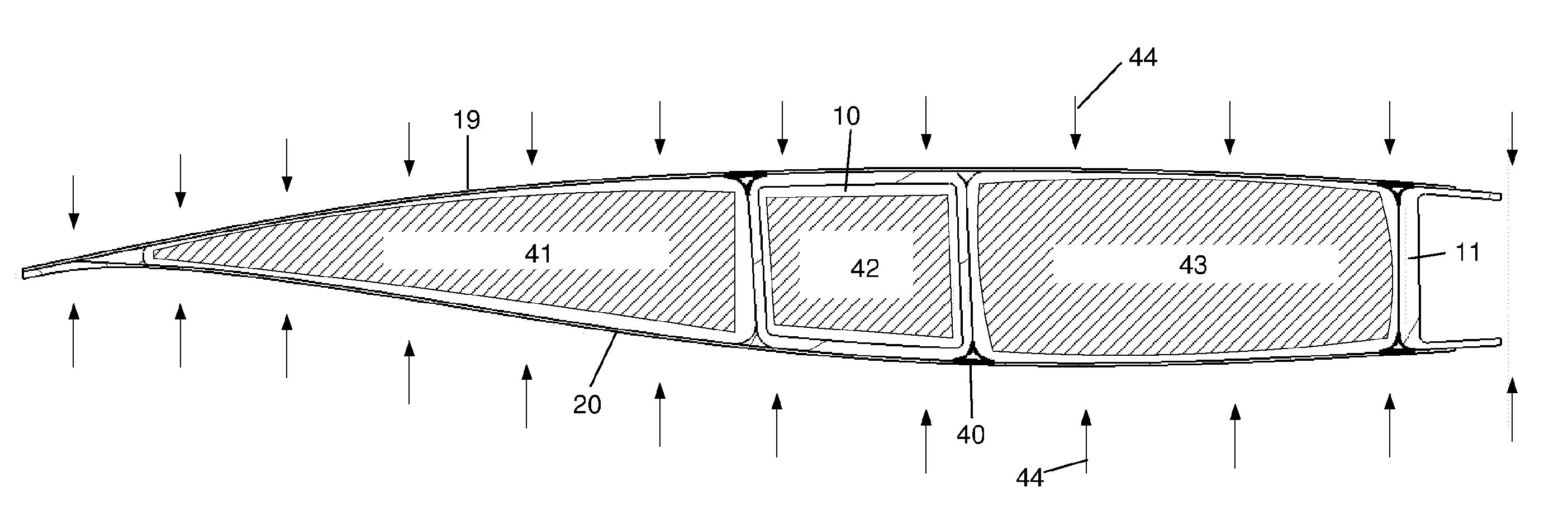
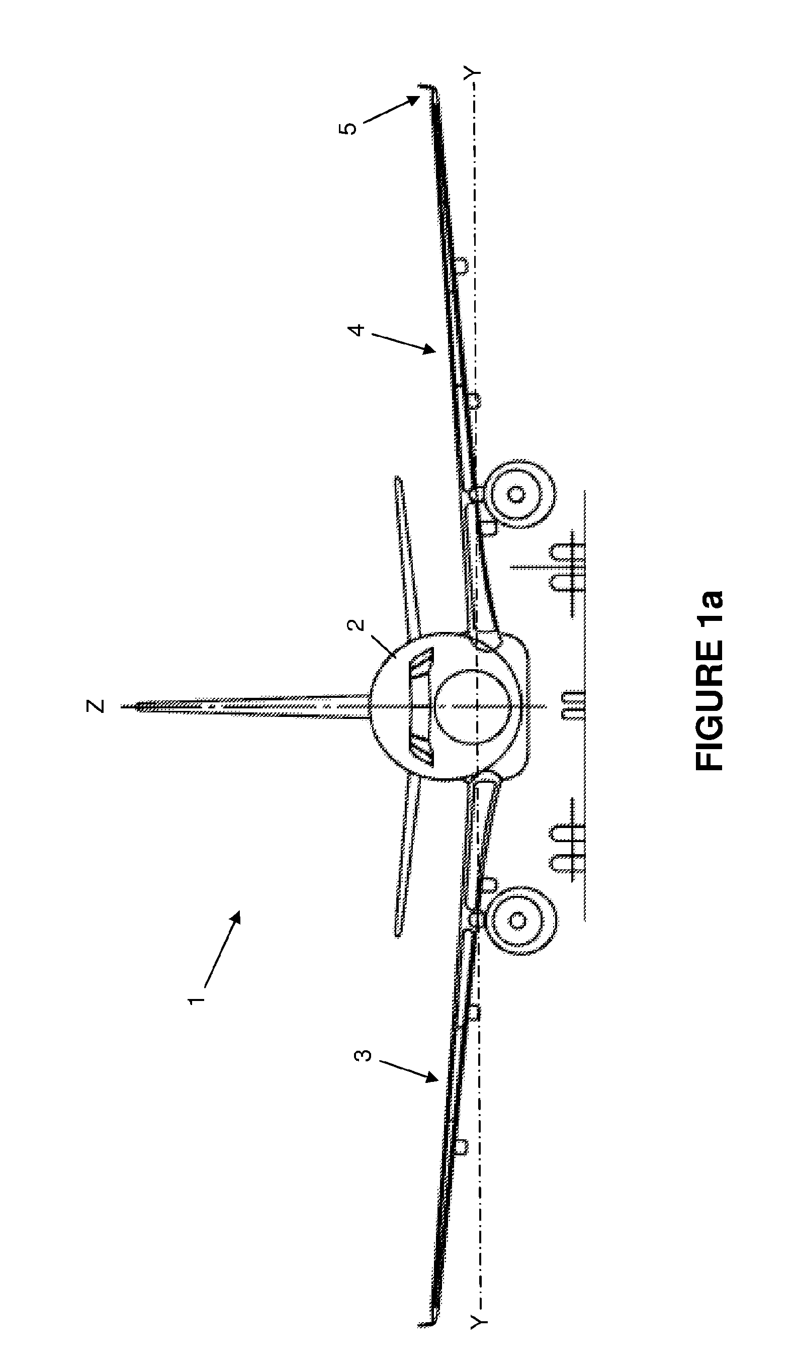
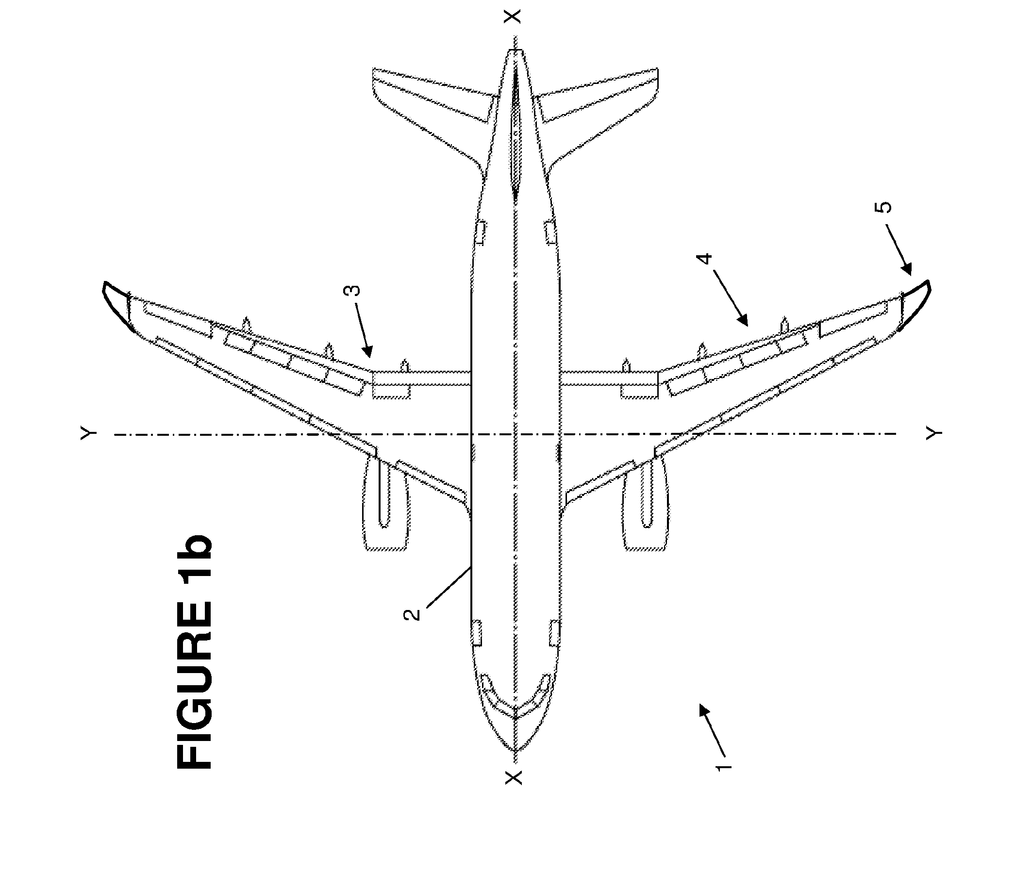
[0047]FIGS. 1a and 1b show an aircraft 1 with a fuselage 2 carrying a pair of wings 3,4. The aircraft has a horizontal fore / aft axis (labelled X) and a horizontal inboard / outboard axis (labelled Y) normal to the fore / aft axis. Each wing has a winglet and the winglet 5 at the tip of the port wing 4 is shown in Figure lc. The port wing 4 comprises a main wing element 6 with a tip 7, and a winglet 5 attached to the tip. The main wing element 6 has front and rear spars running along its full span from a root near the fuselage 2 to its tip 7. Only the webs 8,9 of these spars are shown in FIG. 1 but they also have spar caps which could point in (towards the other spar) or out. A fuel tank is housed in the main wing element 6 between the spar webs 8,9.

[0048]The winglet 5 has a main (rear) spar 10 and a front spar 11. The main spar 10 extends from a root 10a to a tip 10b which is short of a tip 5a of the winglet 5 so it does not run along the full span of the winglet. The front spar 11 ext...


PUM

PropertyMeasurementUnit
Angleaaaaaaaaaa
Heightaaaaaaaaaa

Abstract

A winglet comprising a tubular main spar with forward and aft main spar webs joined by upper and lower main spar caps; a front spar with a front spar web, an upper front spar cap, and a lower front spar cap; an upper skin joined to the upper main spar cap and the upper front spar cap; and a lower skin joined to the lower main spar cap and the lower front spar cap. The winglet is manufactured by co-curing the upper skin to the upper main spar cap and the upper front spar cap; and co-curing the lower skin to the lower main spar cap and the lower front spar cap.

Description

FIELD OF THE INVENTION[0001]The present invention relates to a winglet, an aircraft wing comprising a winglet, and a method of manufacturing a winglet.BACKGROUND OF THE INVENTION[0002]In the large civil aircraft aviation industry the growth in size of wing tip devices over the years as a result of drive to increase wing efficiency through reduction of drag has lead to technical challenges related to the load transfer and efficient joint technology between the wing tip device and wing. Existing large civil aircraft wing tip attachment methods, such as that described in U.S. Pat. No. 7,975,965 B2, are generally made up of a ‘back-to-back’ rib solution where the loads are transferred across a joint utilising the chord depth of the local wing section.[0003]An innovative solution created to decouple the limitations of load transfer through local chord depth is described in US 2012 / 0112005 A1. This idea proposes a joint concept that utilises a ‘main beam’ structure to carry the primary wi...

Claims


Application Information

Patent Timeline
IPC IPC(8): B64C23/06B32B38/18
CPCB64C23/065B32B2305/72B32B38/1866B29C70/222B64F5/10B64C23/069B64C3/185Y02T50/10Y02T50/40B29C70/302B29C70/32B29L2031/3085
Inventor FONG, TONYAXFORD, TIMOTHYCHAUSSEE, JULIEN
Owner AIRBUS OPERATIONS LTD
Why Eureka
Try Eureka