
Mobile terminal charger and vehicle equipped with same

Active Publication Date: 2016-03-17
PANASONIC INTELLECTUAL PROPERTY MANAGEMENT CO LTD
View PDF7 Cites 2 Cited by
  • Summary
  • Abstract
  • Description
  • Claims
  • Application Information

AI Technical Summary

Benefits of technology

The present invention helps move the charging coil to the mobile terminal position more precisely.

Problems solved by technology

Functions of a mobile terminal such as a mobile phone and the like have become extremely high, and along with this, power consumption has been increasing.

Method used


Image

  • Mobile terminal charger and vehicle equipped with same
  • Mobile terminal charger and vehicle equipped with same
  • Mobile terminal charger and vehicle equipped with same

Examples


first exemplary embodiment

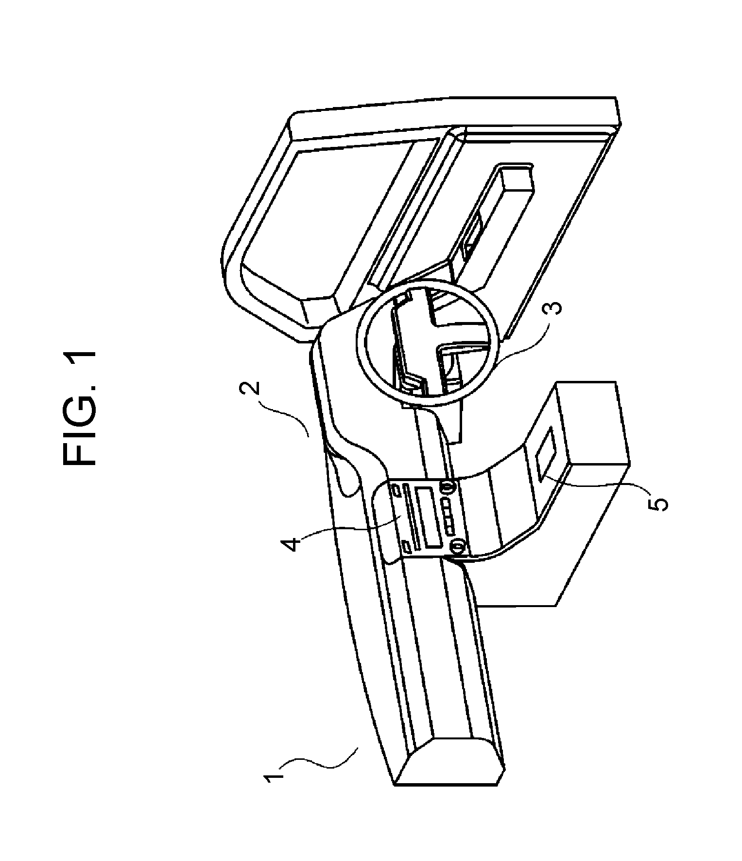
[0039]In FIG. 1, handle 3 is installed in a front portion of interior 2 of vehicle 1.

[0040]Moreover, electronic device 4 that reproduces music and video, and displays car navigation video is installed at the side of handle 3.

[0041]Furthermore, mobile terminal charger 5 is installed at the rear of electronic device 4 in interior 2.

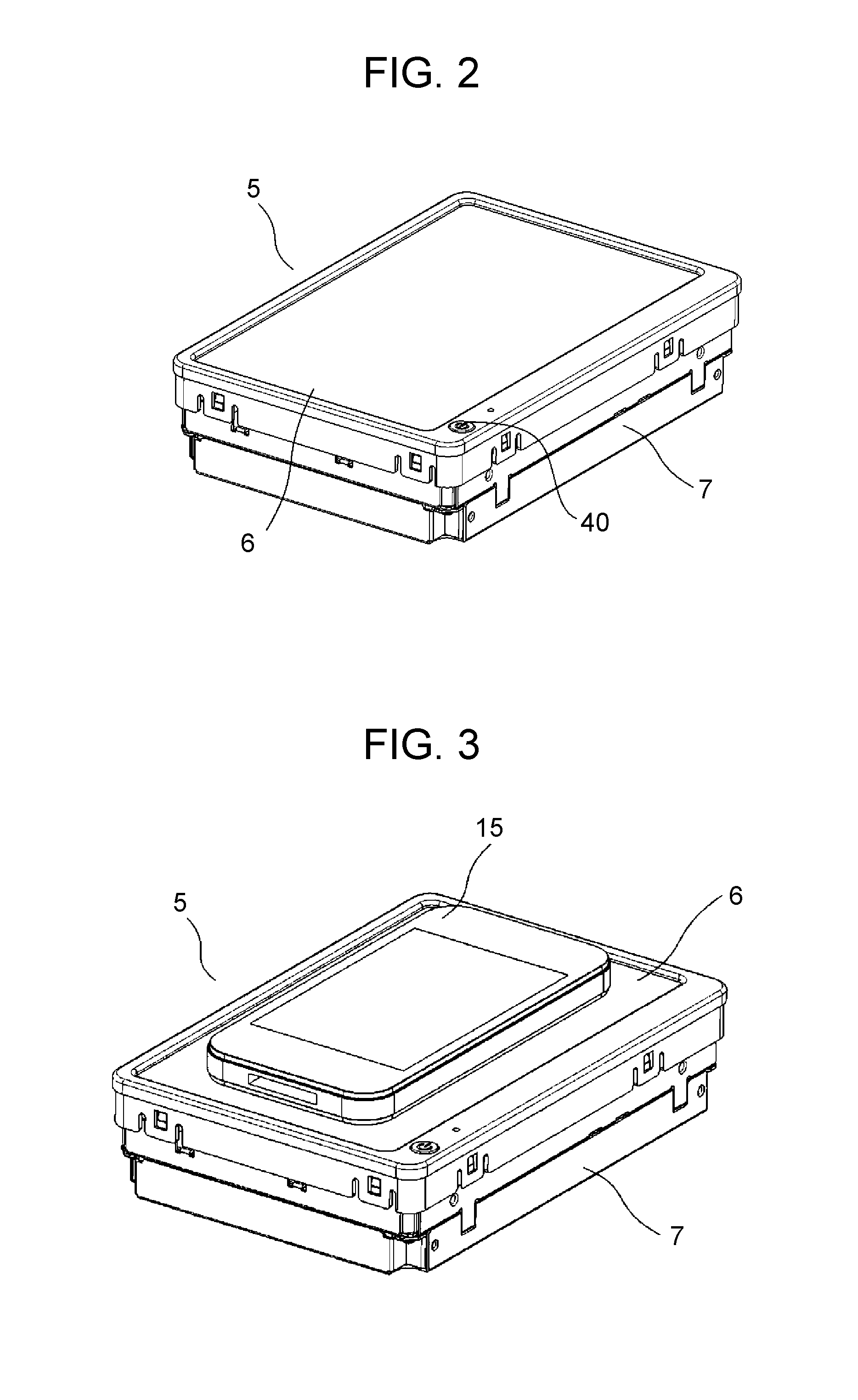
[0042]As shown in FIGS. 2 to 6, mobile terminal charger 5 includes box-shaped body case 7 with mobile terminal installation plate 6 disposed in an upper surface of body case 7, charging coil 8 provided movably in a horizontal direction in a state opposed to a lower surface side of mobile terminal installation plate 6, driving means 9 for moving charging coil 8 in the horizontal direction in opposition to the lower surface side of mobile terminal installation plate 6, and control means (10 in FIG. 9) connected to driving means 9 and charging coil 8. Charging coil 8, driving means 9, and control means 10 are provided in body case 7.

[0043]Hereinafter, the resp...


PUM


Abstract

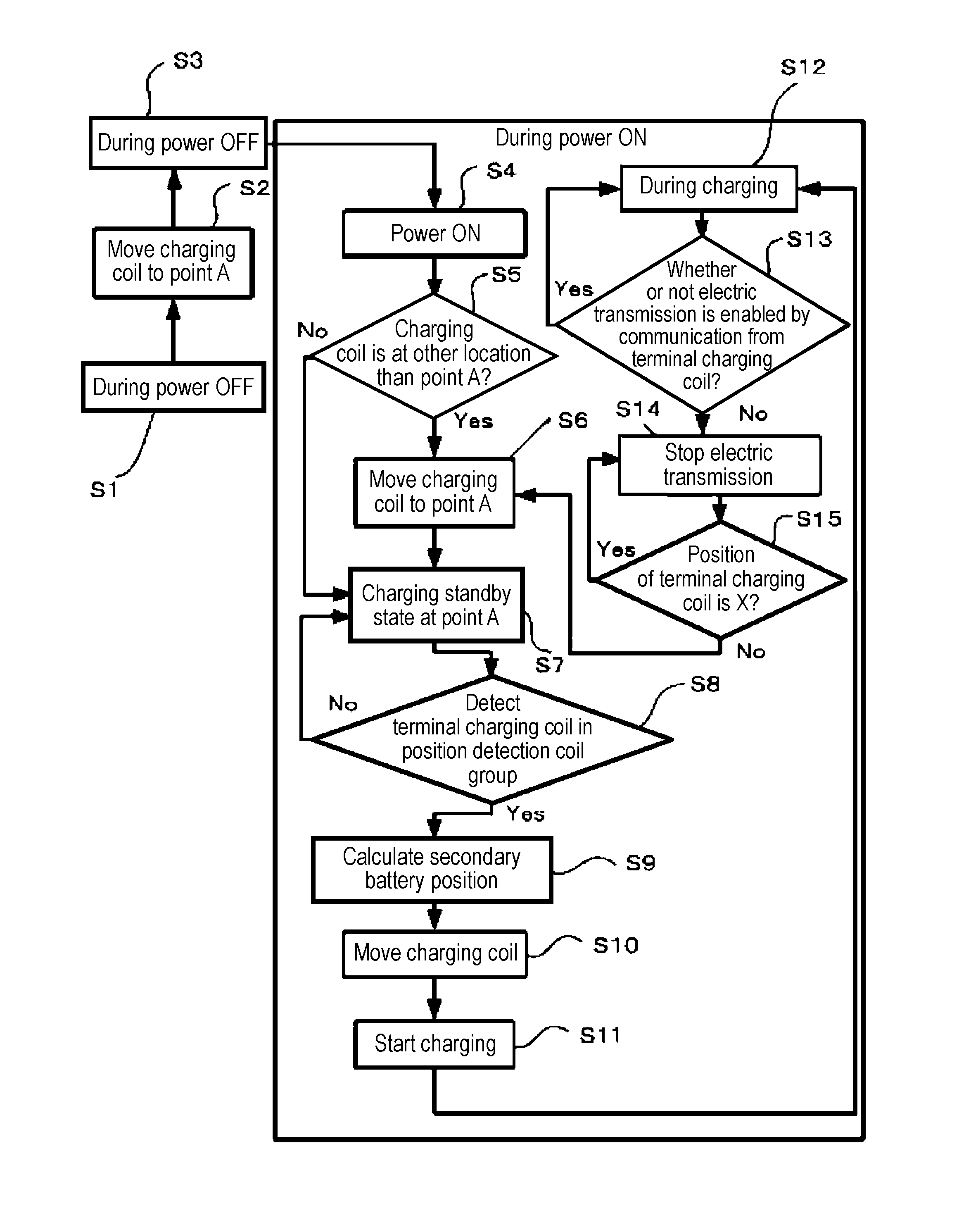
In control means (10), a position of a mobile terminal (15) on an upper surface of a mobile terminal installation plate (6) is detected a plurality of times by a position detection coil (14) used as detection means, and when a previous detected position and a subsequent (referred to as next) detected position are the same, a charging coil (8) is moved by motors (28), (33) used as driving means to a charging position opposed to the previous detected position or the next detected position detected by the position detection coil (14), and the charging is then started.

Description

TECHNICAL FIELD[0001]The present invention relates to a mobile terminal charger to charge a mobile terminal such as a mobile phone and the like, and a vehicle equipped with the same.BACKGROUND ART[0002]Functions of a mobile terminal such as a mobile phone and the like have become extremely high, and along with this, power consumption has been increasing.[0003]Accordingly, it has been demanded that charging is enabled in various places including a vehicle, and as a tendency in recent years, a mobile terminal that can perform so-called contactless charging without using a cable has been attracting attention.[0004]As a mobile terminal charger that meets the above-described demand, the following has been proposed.[0005]That is, the mobile terminal charger is formed so as to include a body case with a mobile terminal installation plate disposed in an upper surface of the body case, a charging coil provided movably in opposition to a lower surface side of the mobile terminal installation ...

Claims


Application Information

Patent Timeline
IPC IPC(8): H02J7/00H02J7/02
CPCH02J7/025H02J7/0044H02J50/90H02J50/10
Inventor TOJO, YUKI
Owner PANASONIC INTELLECTUAL PROPERTY MANAGEMENT CO LTD
Learn More