Motor-driven electric generator

Inactive Publication Date: 2016-03-17
YEH KING CHUAN
View PDF1 Cites 1 Cited by
  • Summary
  • Abstract
  • Description
  • Claims
  • Application Information

AI Technical Summary

Benefits of technology

[0006]Therefore it is a primary object of the present invention to provide a motor-driven electric generator in which a power generating device is driven by a motor. The small power is used to initiate the motor and further drive the power

Problems solved by technology

However, these power sources require a large amount of force for driving generators to produce power.
During the driving process, environmental pollutions are produced.
For example, air and the environment are polluted by cloud of dust emitted during thermal power generatio

Method used


Image

  • Motor-driven electric generator
  • Motor-driven electric generator
  • Motor-driven electric generator

Examples


Embodiment Construction

[0015]Please refer to following embodiments for details, features and effects of the present invention.

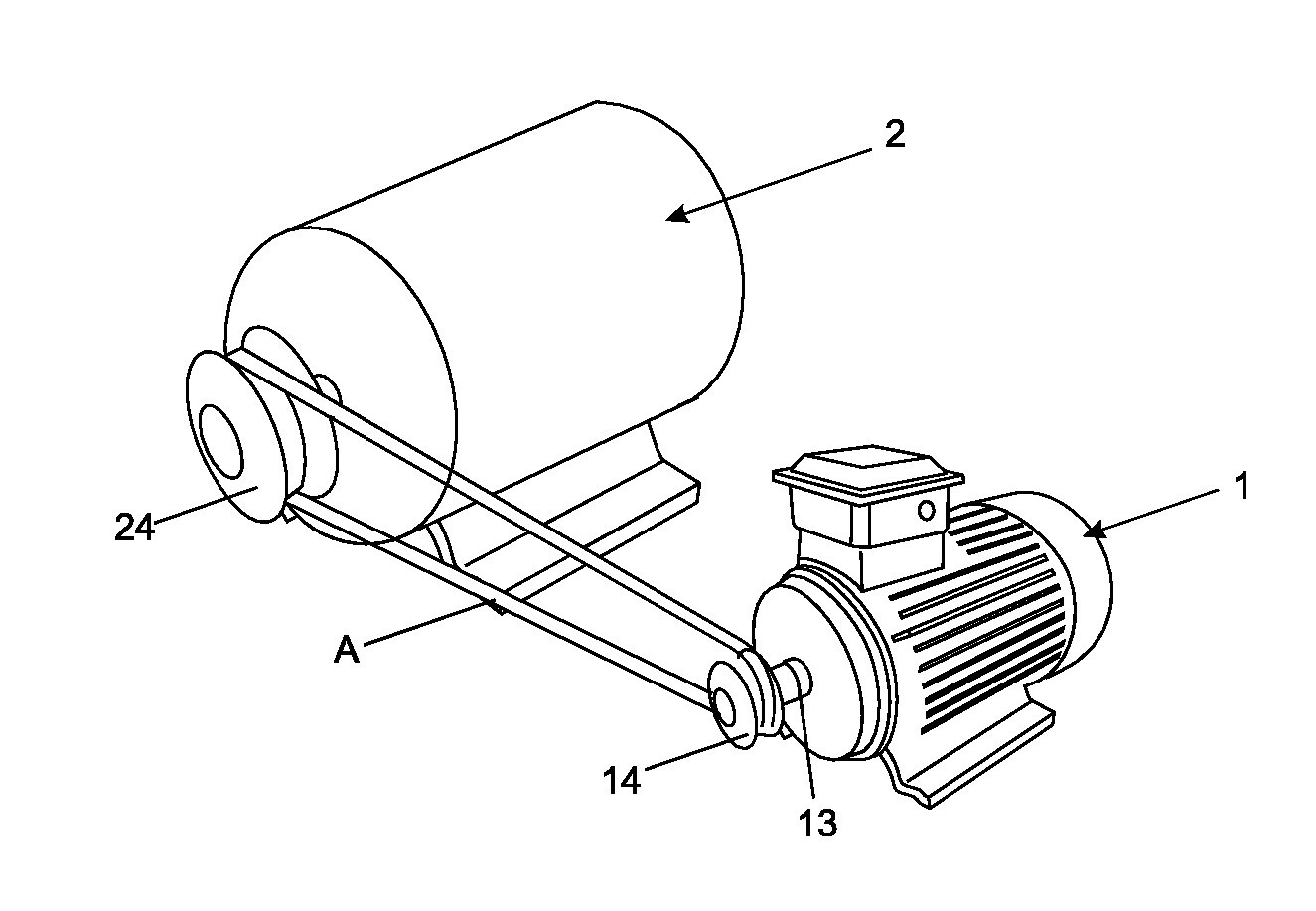
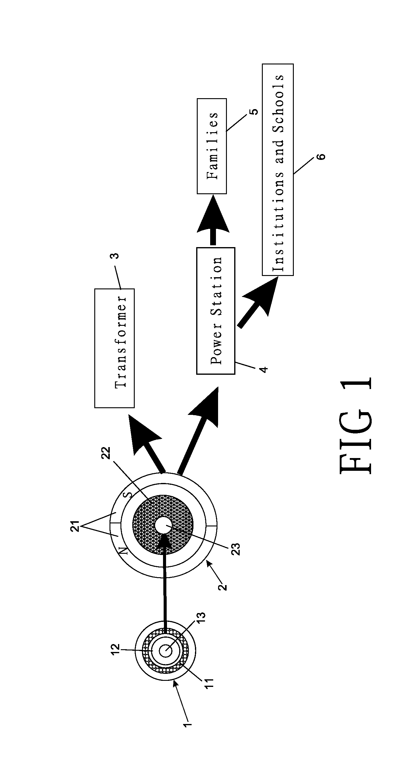
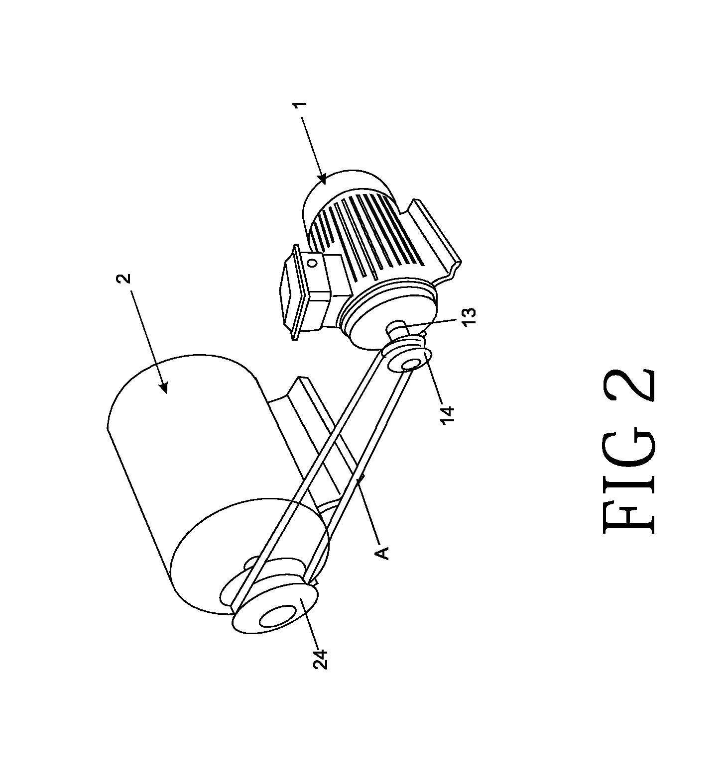
[0016]Refer to FIG. 1, a schematic drawing showing structure of an embodiment according to the present invention is revealed. As to the FIG. 2, it's a perspective view of an embodiment of the present invention.

[0017]Refer to FIG. 1 and FIG. 2, a motor-driven electric generator of the present invention includes a motor 1 and a power generating device 2.

[0018]The motor consists of an outer coil set 11, a rotor 12, a rotating shaft 13 and a first inertia flywheel 14. The outer coil set 11 is disposed around the rotor 12 while the rotating shaft 13 is arranged at the center of the rotor 12. After the outer coil set 11 being applied with a voltage, the rotor 12 is rotated so as to drive the rotating shaft 13 to rotate. This is the structure of a general motor 1.

[0019]The power generating device 2 is composed of a magnetic set 21, an inner coil set 22, a drive shaft 23 and a second inert...


PUM


Abstract

A motor-driven electric generator is revealed. The motor-driven electric generator includes a motor and a power generating device. The motor-driven electric generator features on that the power generating device is driven by the motor so as to convert rotational kinetic energy of the motor to electricity.

Description

NOTICE OF COPYRIGHT[0001]A portion of the disclosure of this patent document contains material which is subject to copyright protection. The copyright owner has no objection to any reproduction by anyone of the patent disclosure, as it appears in the United States Patent and Trademark Office patent files or records, but otherwise reserves all copyright rights whatsoever.BACKGROUND OF THE PRESENT INVENTION[0002]1. Field of Invention[0003]The present invention relates to a motor-driven electric generator, especially to a power generating device that is driven by a motor.[0004]2. Description of Related Arts[0005]Nowadays, electricity is generated by solar energy, wind power, thermal power, hydro power, nuclear power, fuels, etc. However, these power sources require a large amount of force for driving generators to produce power. During the driving process, environmental pollutions are produced. For example, air and the environment are polluted by cloud of dust emitted during thermal po...

Claims


Application Information

Patent Timeline
IPC IPC(8): H02K47/20H02K7/02H02K7/10H02K7/116
CPCH02K47/20H02K7/1004H02K53/00H02K7/02Y10S74/09H02K7/116
Inventor YEH, KING, CHUAN
Owner YEH KING CHUAN
Why Eureka
Try Eureka