System and method for crushing

a crushing system and crushing technology, applied in the field of crushers, can solve the problems of unfilled beverage bottles or containers, unfavorable recycling, and many plastics that take a very long time to biodegrade, and achieve the effects of reducing the long-term reducing the cost of the crusher, and reducing the amount of energy

Active Publication Date: 2012-06-14
KOMAR IND LLC
View PDF7 Cites 4 Cited by
  • Summary
  • Abstract
  • Description
  • Claims
  • Application Information

AI Technical Summary

Benefits of technology

[0002]Exemplary embodiments of the invention are related to a crusher. A crusher may also be known as a compactor. More particularly, exemplary embodiments may include a crusher having an inverse tapered shaft (i.e., reverse tapered shaft) that may utilize a smaller amount of energy than known crushers. A further exemplary embodiment relates to a crusher that includes components that may be more easily replaced than conventional screw crushers to reduce long-term cost of the crusher during use thereof. Also, the screw crusher may facilitate the movement of compacted or compressed material better than known crushers.

Problems solved by technology

Many plastics take a very long period of time to biodegrade, if they biodegrade.
Furthermore, certain types of lightweight plastics may not only float on water, but may also blow in the wind, causing an abundant amount of litter, especially along shores and waterways.
Additionally, in certain manufacturing settings when plastic products, for example, plastic beverage bottles, do not meet desired characteristics and / or tolerances, the filled or unfilled beverage bottles or containers may need to be recycled.
Known crushers may not adequately address the aforementioned needs.
This is particularly problematic with filled containers.
Among other things, this can lead to increased recycling time and costs.
For example, uncrushed containers may necessitate increased time in a baling machine in order to crush the previously uncrushed containers.
The requirement of specific crushers for each different material and / or product leads to added overhead costs to companies that wish to crush or compact multiple different materials and / or products using a singular machine.
Furthermore, known crushers are not self-cleaning when in use.
For example, known crushers commonly become clogged with scraps of various sorts (e.g., labels or other parts of the material being processed) after a period of use.
The material can accumulate and eventually hinder or prevent further use of known crushers.
This adds both time and cost to crushing multiple types of different materials.
The known screw crushers and related methods are less than ideal for compressing or compacting materials.
One of the main problems that occur during the compaction process is that the mechanical components used to contact the plastic throughout the screw compaction process may wear due to high friction, creating undesirable tolerances between components of the crusher.
This is especially true when known screw crushers continuously run for extended periods of time, or in situations where there is high friction within the screw crusher.
The high friction may also demand higher power input to the crusher.
Crushers that use screw compaction have an especially inherent problem with wear of components due to the friction within the chamber and other areas.
The friction between the material and a portion of the chamber may lead to undesirable tolerances between components of the crusher.
Ceasing the continuous operation of the crusher may add extra time and cost to the recycling process.
Additionally, in some instances, total compaction of a product may not be desired due to higher energy requirements or increased wear on the equipment.

Method used


Image

  • System and method for crushing
  • System and method for crushing
  • System and method for crushing

Examples


Embodiment Construction

)

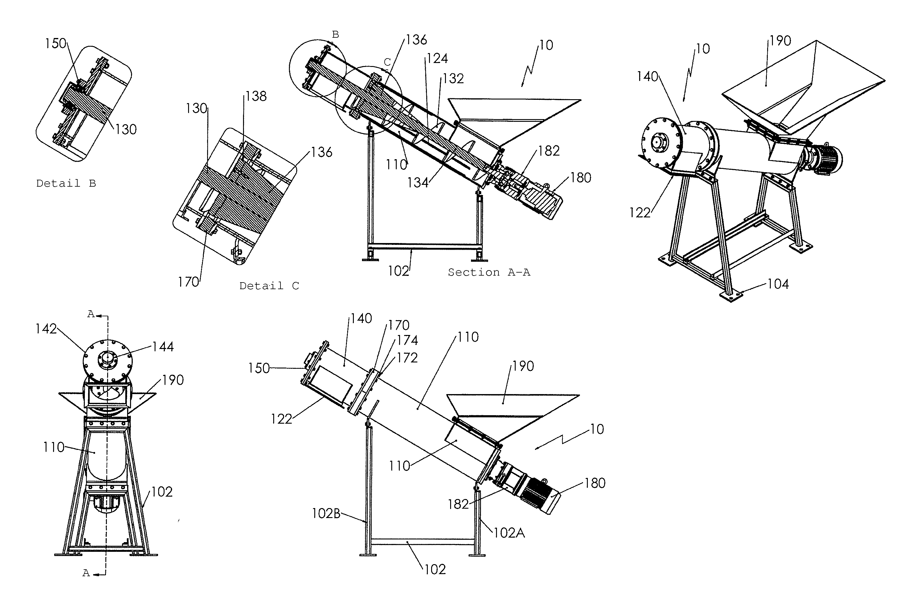
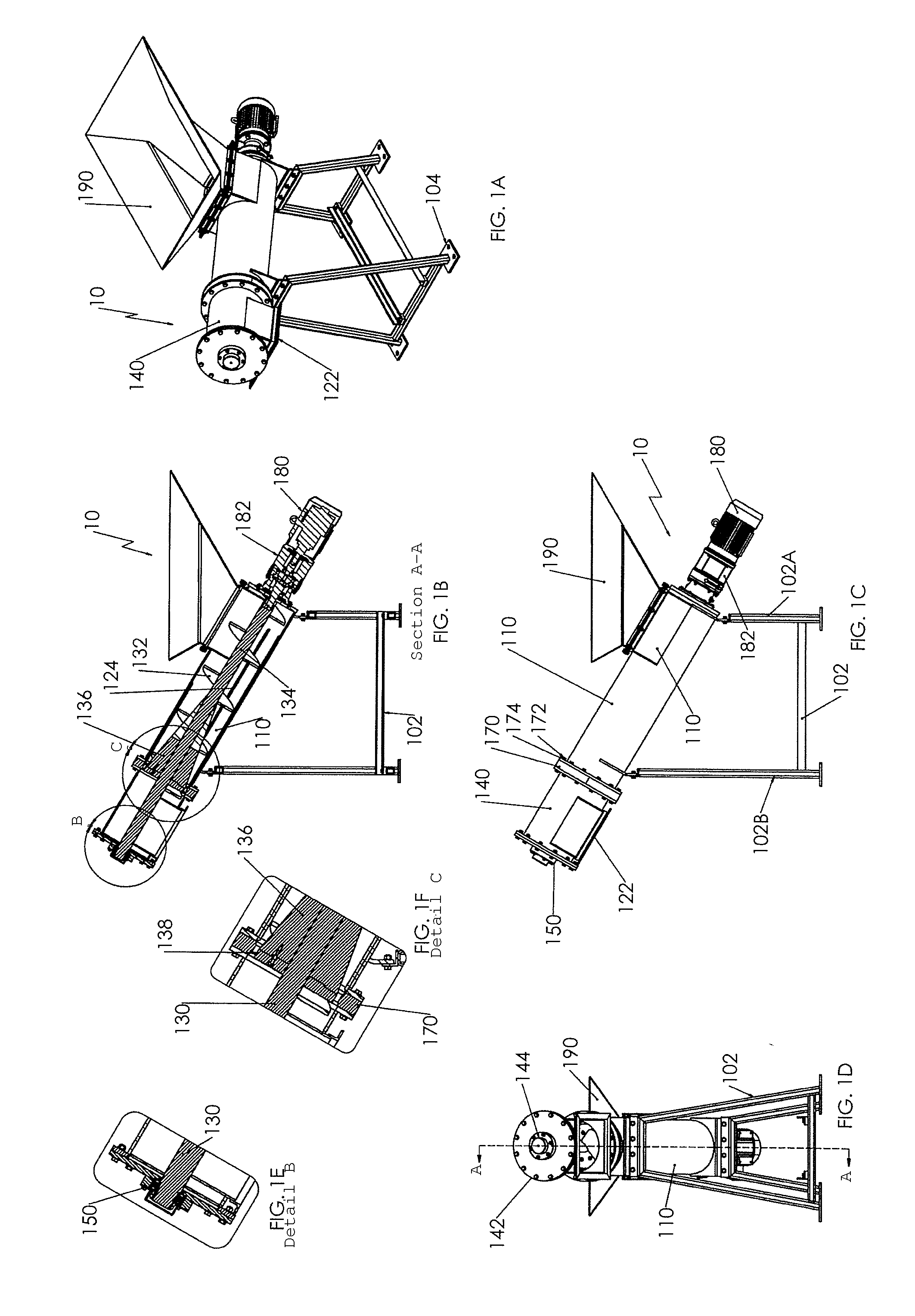
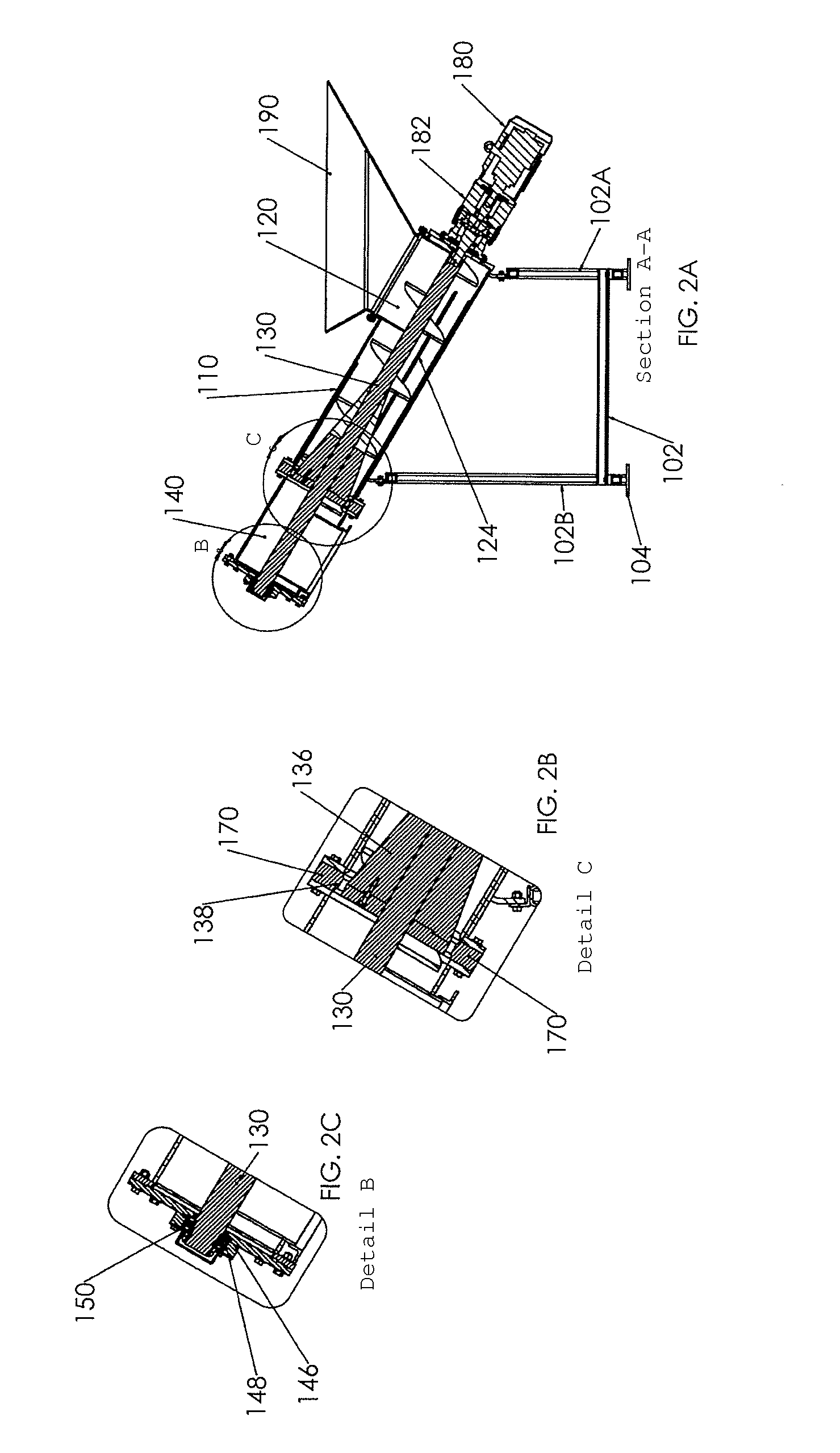
[0031]As seen in FIGS. 1-11, exemplary embodiments of a crusher 10 that may be adapted to compact plastics or other materials are illustrated. Exemplary embodiments may include a frame 102 with a proximal end 102A and a distal end 102B such that mounting bodies 104 are attached to the frame 102. In other exemplary embodiments, the frame 102 may be adapted to move on different surfaces with the inclusion of wheels or other devices that would facilitate movement thereof.

[0032]Exemplary embodiments of the crusher 10 may include a compaction chamber 110 that is mounted to the frame 102. The compaction chamber 110 may include one or more mounting bodies 112 that extend from the periphery thereof that facilitate mounting of the compaction chamber 110 with the frame 102. The compaction chamber 110 may be associated with the frame 102 by any number of means. However, in one example, threaded fasteners may facilitate the association. The compaction chamber 110 may be any number of geometrie...


PUM

PropertyMeasurementUnit
diameteraaaaaaaaaa
lengthaaaaaaaaaa
sizeaaaaaaaaaa

Abstract

Exemplary embodiments are for a system for crushing a material that may include a compaction chamber and a screw assembly that generally extends between the proximal and distal ends of the compaction chamber. A portion of the screw assembly increases in diameter along a length of the shaft of the screw assembly such that the system is configured to crush material between the compaction chamber and the portion of the screw assembly that increases in diameter. The portion of the screw assembly that increases in diameter may be integral with the shaft of the screw assembly. An exemplary embodiment of the system may also include at least one wear member that is removably associated with the distal portion of the compaction chamber such that the wear member may assist with the crushing of material.

Description

CROSS-REFERENCE TO RELATED APPLICATIONS[0001]This application claims the benefit of U.S. Provisional Application No. 61 / 421,505, filed Dec. 9, 2010, which is hereby incorporated by reference as if fully recited herein.BACKGROUND AND SUMMARY OF THE INVENTION[0002]Exemplary embodiments of the invention are related to a crusher. A crusher may also be known as a compactor. More particularly, exemplary embodiments may include a crusher having an inverse tapered shaft (i.e., reverse tapered shaft) that may utilize a smaller amount of energy than known crushers. A further exemplary embodiment relates to a crusher that includes components that may be more easily replaced than conventional screw crushers to reduce long-term cost of the crusher during use thereof. Also, the screw crusher may facilitate the movement of compacted or compressed material better than known crushers.[0003]The amount of materials ending up in landfills is continuously increasing. As the scarcity of landfill space in...

Claims


Application Information

Patent Timeline
Patent Type & Authority Applications(United States)
IPC IPC(8): B02C19/00
CPCB29B17/0052B30B9/14B30B9/128Y02W30/62
Inventor KOENIG, MARK E.KOENIG, LARRY E.
Owner KOMAR IND LLC
Why Eureka
Try Eureka