A Load Carrying Bar

a load carrying and bar technology, applied in the direction of transportation and packaging, vehicle components, supplementary fittings, etc., can solve the problems of increasing wind noise and wind resistance, affecting the lacquer of the automobile, and the solution is not very sophisticated, so as to reduce air turbulence

Active Publication Date: 2016-03-24
THULE SWEDEN AB
View PDF13 Cites 4 Cited by
  • Summary
  • Abstract
  • Description
  • Claims
  • Application Information

AI Technical Summary

Benefits of technology

[0006]It is an object of the present invention to provide for a solution, or to at least reduce some of the drawbacks of the known prior art, or to provide for a useful alternative. The objects are at least partly met by a load carrying bar for a roof rack, the load carrying bar having a length, a height and a width. The load carrying bar comprises a channel with an opening for receiving a fastening member of a load carrying bar accessory. A cover is arranged to seal at least a portion of the opening of the channel of the load carrying bar, e.g. to reduce air turbulence around the channel. The cover comprises an attachment portion for attaching the cover to the load carrying bar and channel sealing portion adapted to substantially seal at least a portion of the opening of the channel of the load carrying bar.

Problems solved by technology

Such channels are however associated with numerous problems such as wind turbulence increasing the wind noise and wind resistance.
They can also collect dirt or rubble, which in turn accidentally could damage the lacquer of the automobile.
The solution is however not very sophisticated as it requires the user to measure and to remove parts of the sealing strip in order to allow the fastening means to fit in the channel.
There is a risk that the cover infill may be pinched between the fastening means and the floor of the channel.
This can damage the cover infill when the fastening means is displaced along the length of the load carrying bar in the channel as the fastening means may rest on the cover infill instead of resting on the load carrying bar itself before being readily attached to the load carrying bar.

Method used


Image

  • A Load Carrying Bar
  • A Load Carrying Bar
  • A Load Carrying Bar

Examples


Embodiment Construction

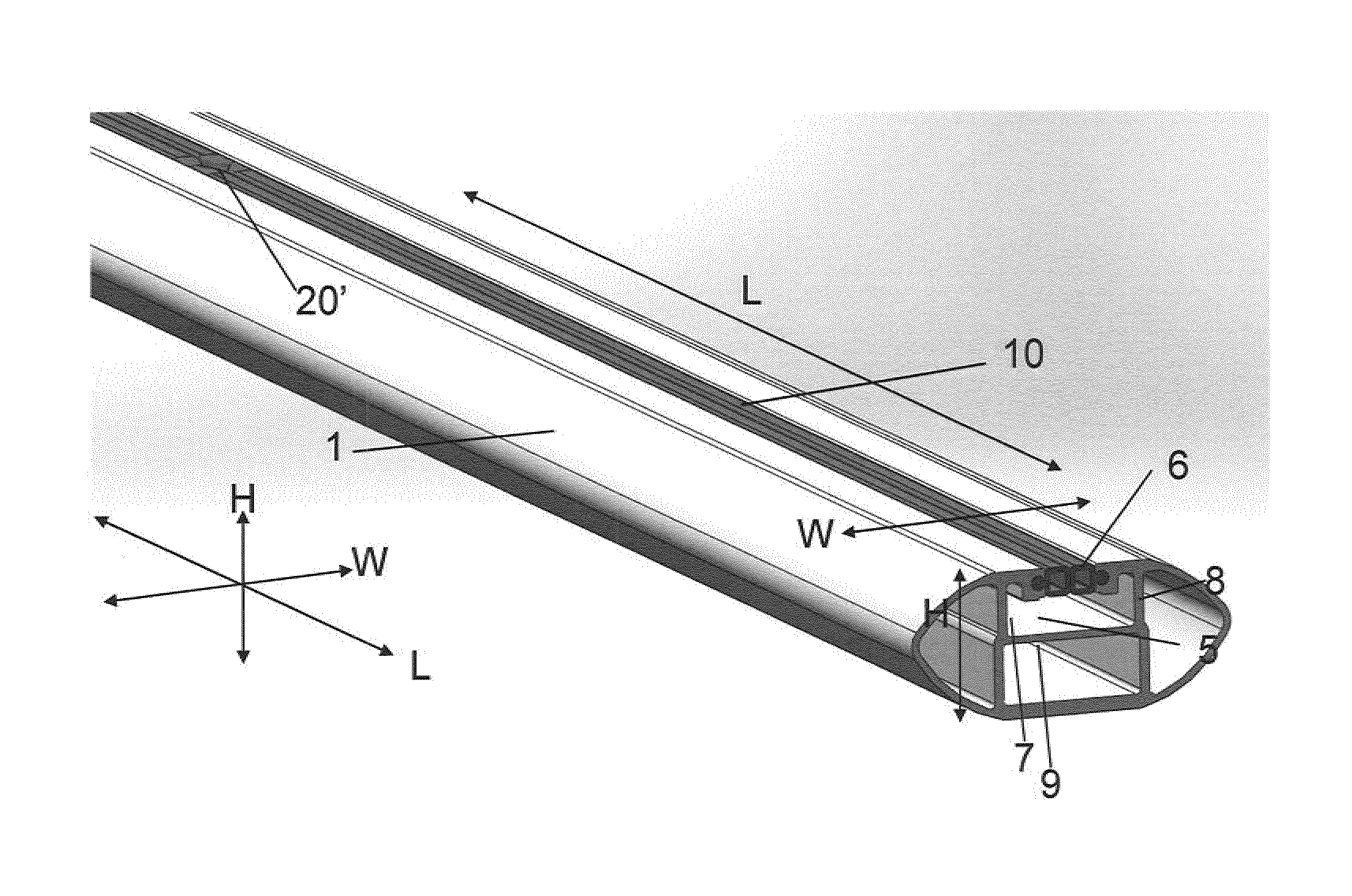
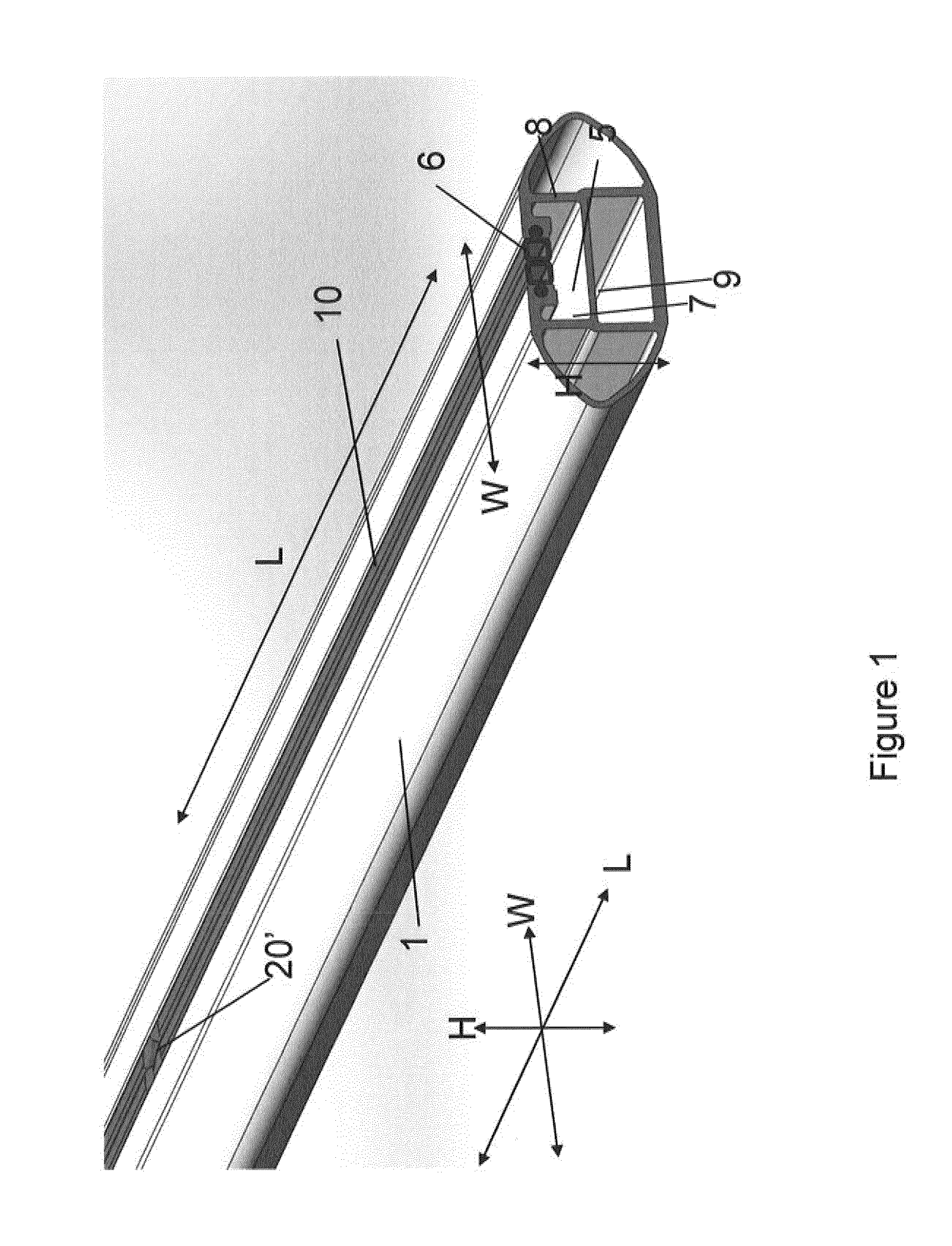
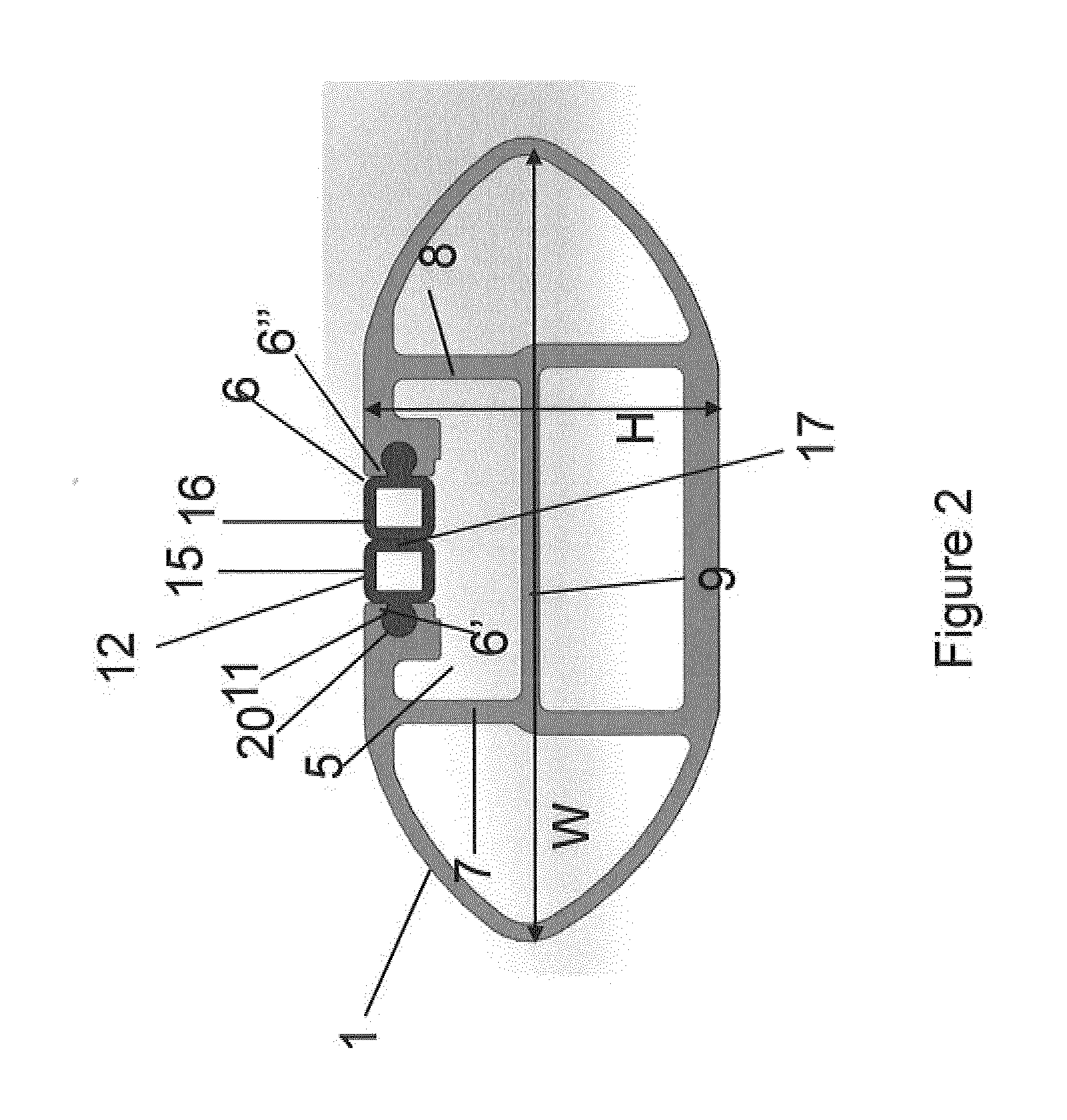
[0037]FIG. 1 shows a load carrying bar 1 for a roof rack. A roof rack is intended during use to be mounted to e.g. the roof of an automobile such as a car or truck. A first and a second load carrier foot are generally positioned on each side of the automobile so that the load carrying bar 1 extends transversely across the roof of the automobile. The load carrying bar 1 is formed by extruded material such as aluminum and has a substantially oval cross section as can be seen in FIGS. 1 and 3a-3b for example with openings at each end (only one end shown in FIG. 1). The ends of the load carrying bar 1 can be sealed if desired by a separate lid, plug or by parts of the load carrier foot for example.

[0038]The load carrying bar 1 comprises a channel 5 for receiving a fastening member for a load carrying accessory. A load carrying accessory can be a roof box, a bicycle carrier, a luggage carrier, a ski carrier, or any other load carrier suitable to mount on a roof rack. The fastening member...


PUM


Abstract

A load carrying bar including a channel with an opening. The channel is adapted to receive a fastening member for fasten a load carrying bar accessory to the load carrying bar. A cover is arranged to seal the opening of the channel. The cover is adapted to be deformed in the proximity of the opening as the fastening member is slid along the length of the channel.

Description

TECHNICAL FIELD[0001]The present invention relates to a load carrying bar comprising a channel with an opening, the channel is adapted for mounting a load carrying bar accessory to the load carrying bar, such as roof box. A cover is arranged in the channel to cover, or seal, the opening of the channel to reduce air turbulence around the channel and the intrusion of dirt in the channel.BACKGROUND OF THE INVENTION[0002]Roof racks comprising load carrying bars mounted to the roof of an automobile via load carrier feet are commonly used to provide for an improved load capacity on automobiles. During recent years, a trend has been that the cross section of the load carrying bars has been improved to reduce wind resistance and noise. One type of improved load carrying bars have a wing like cross section having a low wind resistance and low noise level.[0003]To attach load carrying bar accessories, such as roof box, to a load carrying bar having a wing like cross section, the load carrying...

Claims


Application Information

Patent Timeline
Patent Type & Authority Applications(United States)
IPC IPC(8): B60R9/052B60R9/05
CPCB60R9/05B60R9/052B60R9/058
Inventor FERMAN, MAGNUS
Owner THULE SWEDEN AB
Why Eureka
Try Eureka