Image forming apparatus

a technology of forming apparatus and forming tube, which is applied in the direction of electrographic process apparatus, instruments, optics, etc., can solve the problems of image quality degradation, degrading printed image quality, image quality degradation, etc., to prevent image quality degradation, prevent concentration variation, and prevent the effect of deterioration of toner

Inactive Publication Date: 2016-03-24
CANON KK
View PDF6 Cites 4 Cited by
  • Summary
  • Abstract
  • Description
  • Claims
  • Application Information

AI Technical Summary

Benefits of technology

[0010]The present invention is for solving the issues described above. More specifically, the present invention is directed to providing an image forming apparatus that can prevent image quality degradation from occurring when low coverage rate images are successively formed or when successive low coverage rate image forming is switched to successive high coverage rate image forming. Toner refresh control is executed based on both a first threshold value for preventing deterioration of toner and a second threshold value for preventing concentration variations.

Problems solved by technology

The toner deterioration causes image quality degradation, such as a grainy effect, degrading printed image quality.
When images with a low coverage rate are successively output, not only the image quality degradation due to the toner deterioration described above but also the following problem occurs.
While the low coverage rate images are output, the toner charging amount is likely to be high due to excessive frictional charging between the toner and the carrier because the amount of toner exchanged in the developing device is small.
On the other hand, while the high coverage rate images are output, the toner charging amount is likely to be low because a large amount of toner is consumed and supplied.
However, the refresh control might not be sufficiently effective against the density fluctuation caused by the change in the toner charging amount occurring when the low coverage rate image output is switched to the high coverage rate image output.
More specifically, when the successive low coverage rate image output is performed, the conventional toner refresh control, executed at timing for preventing the image quality degradation due to the toner deterioration, might not be effective enough to prevent the image density fluctuation due to the change in the toner charging amount caused by switching of the coverage rates.
All things considered, an attempt to address the above two issues with the conventional refresh control only might lead to an unnecessarily toner consumption or an insufficient refreshing effect.

Method used


Image

  • Image forming apparatus
  • Image forming apparatus
  • Image forming apparatus

Examples


Embodiment Construction

[0032]An image forming apparatus according to a first exemplary embodiment of the present invention is described in detail below.

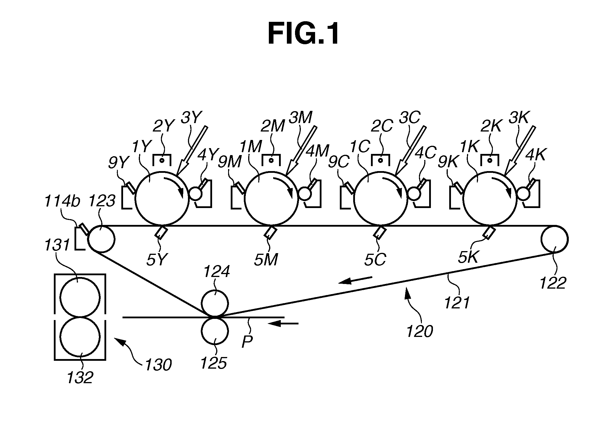
[0033]As illustrated in FIG. 1, an image forming apparatus according to the present exemplary embodiment includes four image forming stations Y, M, C, and K respectively including photosensitive drums 1 (1Y, 1M, 1C, and 1K) as latent image bearing members. An intermediate transfer device 120 is disposed below the image forming stations. In the intermediate transfer device 120, an intermediate transfer belt 121, as an intermediate transfer member, is stretched around rollers 122, 123, and 124, and runs in a direction indicated by an arrow.

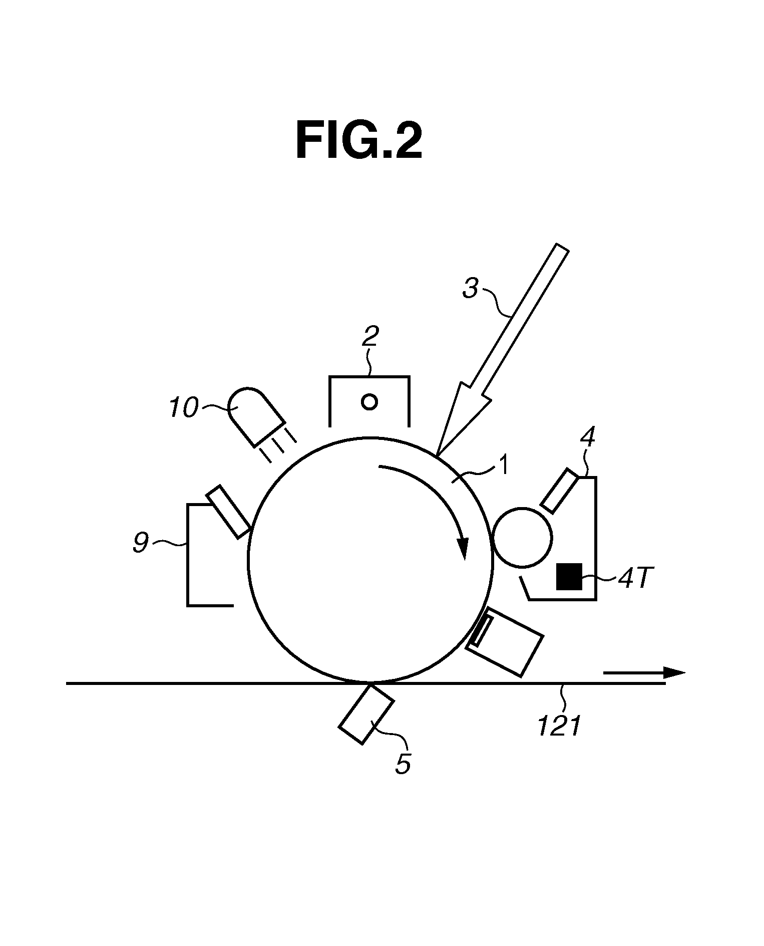
[0034]In the present exemplary embodiment, a surface of each of the photosensitive drums 1 (1Y, 1M, 1C, and 1K), charged by a corresponding one of primary charging devices (2Y, 2M, 2C, and 2K) employing a corona charging system for contactless charging, is exposed by a corresponding one of laser emitting devices 3 (3Y, 3M,...


PUM


Abstract

An image forming apparatus includes an image bearing member, a developing device, a supplying device, and a control unit. The image bearing member bears a latent image. The developing device develops the latent image with a toner. The supplying device supplies toner to the developing device. The control unit executes a discharge operation to consume toner transferred onto the image bearing member from the developing device without transferring the toner onto a recording medium. The control unit executes the discharge operation where first deterioration integrated information exceeds a first executing threshold, and where second deterioration integrated information exceeds a second executing threshold that is larger than the first executing threshold. The control unit acquires the first deterioration information based at least a first deterioration threshold, and acquires the second deterioration information based on at least a second deterioration threshold that is larger than the first deterioration threshold.

Description

BACKGROUND OF THE INVENTION[0001]1. Field of the Invention[0002]The present invention relates to an image forming apparatus including a developing device that develops an electrostatic latent image formed on an image bearing member of an electrophotographic copier, a laser beam printer, or the like, to develop a toner image.[0003]2. Description of the Related Art[0004]In conventional electrophotographic image forming apparatuses, when images with a low coverage rate are successively output, developer is stirred and rubbed for a while in a state where almost no toner is consumed and supplied in a developing device. For example, the developer is stirred by a developer conveyance screw that conveys the developer, and rubbed between a development sleeve and a doctor blade. As a result, an external additive provided to the toner for charge control and flowability control might be separated from the toner or embedded in a toner surface (hereinafter, also referred to as toner deterioration...

Claims


Application Information

Patent Timeline
Patent Type & Authority Applications(United States)
IPC IPC(8): G03G15/00
CPCG03G15/556G03G15/0896G03G15/0844
Inventor AKITA, MASANORITAKAHASHI, KYOSUKEMATSUMOTO, ATSUSHI
Owner CANON KK
Why Eureka
Try Eureka