
Device and method of supporting reduced data transmission bandwidth

a data transmission and data technology, applied in the field of wireless communications, can solve the problems of less computational less and insufficient communication power of mtc ues with the nearest, and achieve the effect of reducing the number of devices and reducing the cost of data transmission

Inactive Publication Date: 2016-03-24
INTEL CORP
View PDF5 Cites 84 Cited by
  • Summary
  • Abstract
  • Description
  • Claims
  • Application Information

AI Technical Summary

Benefits of technology

The patent text discusses a solution for improving communication coverage for low-power devices, such as machine-type communication (MTC) UEs, in cellular networks. The problem is that these devices often have low power and limited energy for communication, and they may be located in areas with poor coverage or isolated geographical areas. The solution involves repeatedly transmitting signals over multiple subframes and physical channels to accumulate energy at the receiving device. The text also describes various embodiments of the network and methods for allocating resources for uplink or downlink data transmission to MTC UES. The technical effect of this solution is to extend the coverage of MTC UES and improve the link budget for communication with them.

Problems solved by technology

MTC UEs pose a particular challenge due to low energy consumption involved in such communication.
In particular, MTC UEs are less computationally powerful and have less power for communication, and many are configured to remain essentially indefinitely in a single location.
Unfortunately, in a number of cases, MTC UEs do not have sufficient power for communications with the nearest serving base station (enhanced Node B (eNB)) with which they communicate.
Similar problems may exist for non-stationary wireless UEs, such as mobile phones, that are disposed in a network area with poor coverage, i.e., one in which the link budget is several dB below typical network values.
Transmission power may not be able to be increased either by a UE or eNB in situations in which UEs are in such areas.

Method used


Image

  • Device and method of supporting reduced data transmission bandwidth
  • Device and method of supporting reduced data transmission bandwidth
  • Device and method of supporting reduced data transmission bandwidth

Examples


Embodiment Construction

[0011]The following description and the drawings sufficiently illustrate specific embodiments to enable those skilled in the art to practice them. Other embodiments may incorporate structural, logical, electrical, process, and other changes. Portions and features of some embodiments may be included in, or substituted for, those of other embodiments. Embodiments set forth in the claims encompass all available equivalents of those claims.

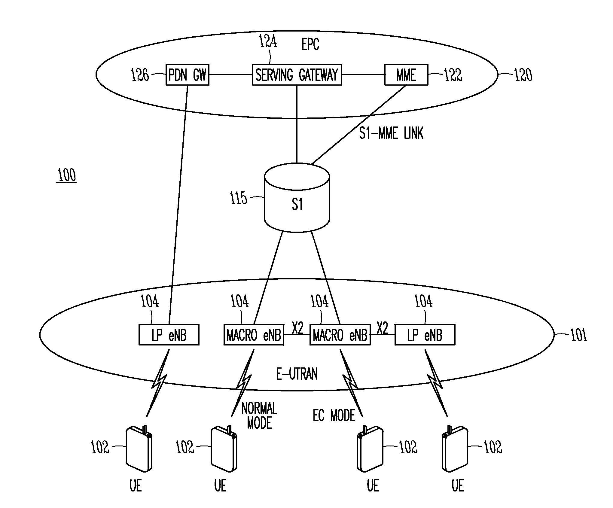
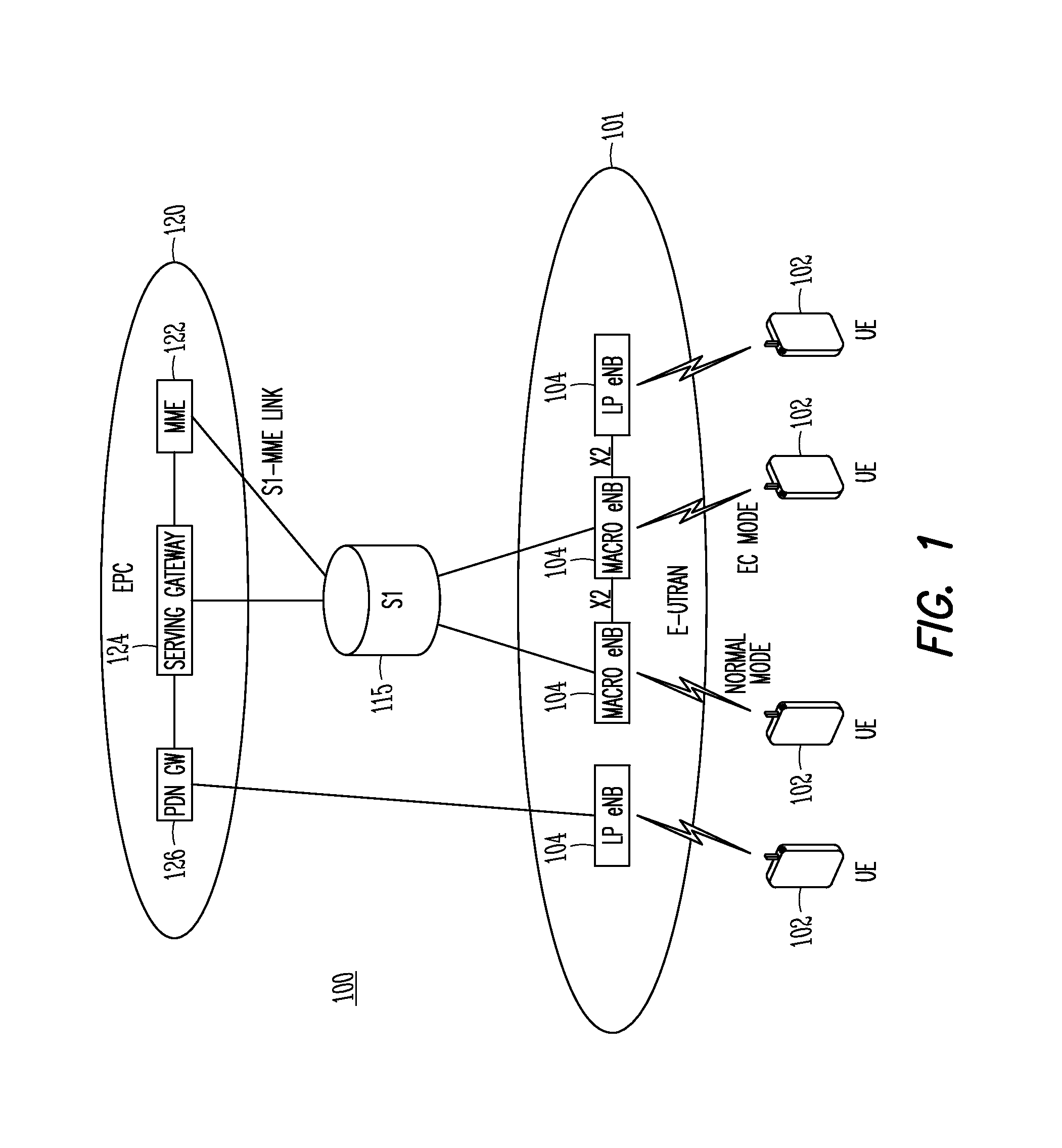
[0012]FIG. 1 is a functional diagram of a 3GPP network in accordance with some embodiments. The network may comprise a radio access network (RAN) (e.g., as depicted, the E-UTRAN or evolved universal terrestrial radio access network) 100 and the core network 120 (e.g., shown as an evolved packet core (EPC)) coupled together through an S1 interface 115. For convenience and brevity sake, only a portion of the core network 120, as well as the RAN 100, is shown.

[0013]The core network 120 includes mobility management entity (MME) 122, serving gateway (servi...


PUM


Abstract

An eNodeB (eNB), user equipment (UE) and method for operating using a reduced data transmission bandwidth are generally described. The UE may receive downlink control information (DCI) that provides a resource allocation (RA) of a reduced physical resource block (PRBmin) of less than 1 PRB for communications in a PRB of a subframe. Whether the RA is localized or distributed may be predefined, configured via system information block or Radio Resource Control signaling, or indicated in the DCI format. The DCI format may specify the resources within the PRB allocated to the UE through a subcarrier block index and total number of subcarrier blocks or a bitmap corresponding to a unique block of subcarriers or block index. An order in a list of cell Radio Network Temporary Identifiers (RNTIs) may be used with a common RNTI to derive the reduced RA from a 1 PRB RA.

Description

PRIORITY CLAIM[0001]This application claims the benefit of priority to U.S. Provisional Patent Application Ser. No. 62 / 052,253, filed Sep. 18, 2014, and entitled “SUPPORT FOR DATA TRANSMISSION BANDWIDTH LESS THAN 1 PRB FOR MTC UES,” which is incorporated herein by reference in its entirety.TECHNICAL FIELD[0002]Embodiments pertain to wireless communications. Some embodiments relate to cellular communication networks including Third Generation Partnership Project Long Term Evolution (3GPP LTE) networks and LTE advanced (LTE-A) networks as well as 4th generation (4G) networks and 5th generation (5G) networks. Some embodiments relate to enhanced coverage communication.BACKGROUND[0003]With the increase in different types of devices communicating over networks to servers and other computing devices, usage of third generation long term evolution (3GPP LTE) systems has increased. In particular, both normal user equipment (UE) such as cell phones and Machine Type Communications (MTC) UEs cur...

Claims


Application Information

Patent Timeline
IPC IPC(8): H04W72/04H04L5/00H04W4/70
CPCH04W72/042H04L5/0007H04W4/005H04W72/0446H04W72/121H04L5/0053H04L5/0094H04W4/70H04W72/0453H04W72/23
Inventor XIONG, GANGHAN, SEUNGHEEFWU, JONG-KAECHATTERJEE, DEBDEEP
Owner INTEL CORP
Learn More