Charge control device using an in-vehicle solar cell

a solar cell and control device technology, applied in the direction of propulsion parts, electric devices, propulsion using engine-driven generators, etc., can solve the problems that the solar panel's solar energy, i.e. renewable energy, cannot be effectively used

Active Publication Date: 2016-03-31
TOYOTA JIDOSHA KK
View PDF5 Cites 18 Cited by
  • Summary
  • Abstract
  • Description
  • Claims
  • Application Information

AI Technical Summary

Benefits of technology

[0015]In accordance with this, when the electric power generated by the in-vehicle solar cell is the predetermined electric power set up based on the total power consumption consumed by the operations of a plurality of the auxiliary machines and a plurality of the electronic control instruments or less, the electric power supply portion can supply the surplus electric power obtained by subtracting the electric power consumed in association with the operation of the charge control portion from the electric power generated by the in-ve

Problems solved by technology

Therefore, when the pumping charge is being carried out, there is a possibility that the elec

Method used


Image

  • Charge control device using an in-vehicle solar cell
  • Charge control device using an in-vehicle solar cell
  • Charge control device using an in-vehicle solar cell

Examples


Embodiment Construction

[0023]Hereafter, a charge control device using an in-vehicle solar cell and according to one embodiment of the present invention (hereafter, simply referred to as “the present device”) will be explained, referring to drawings.

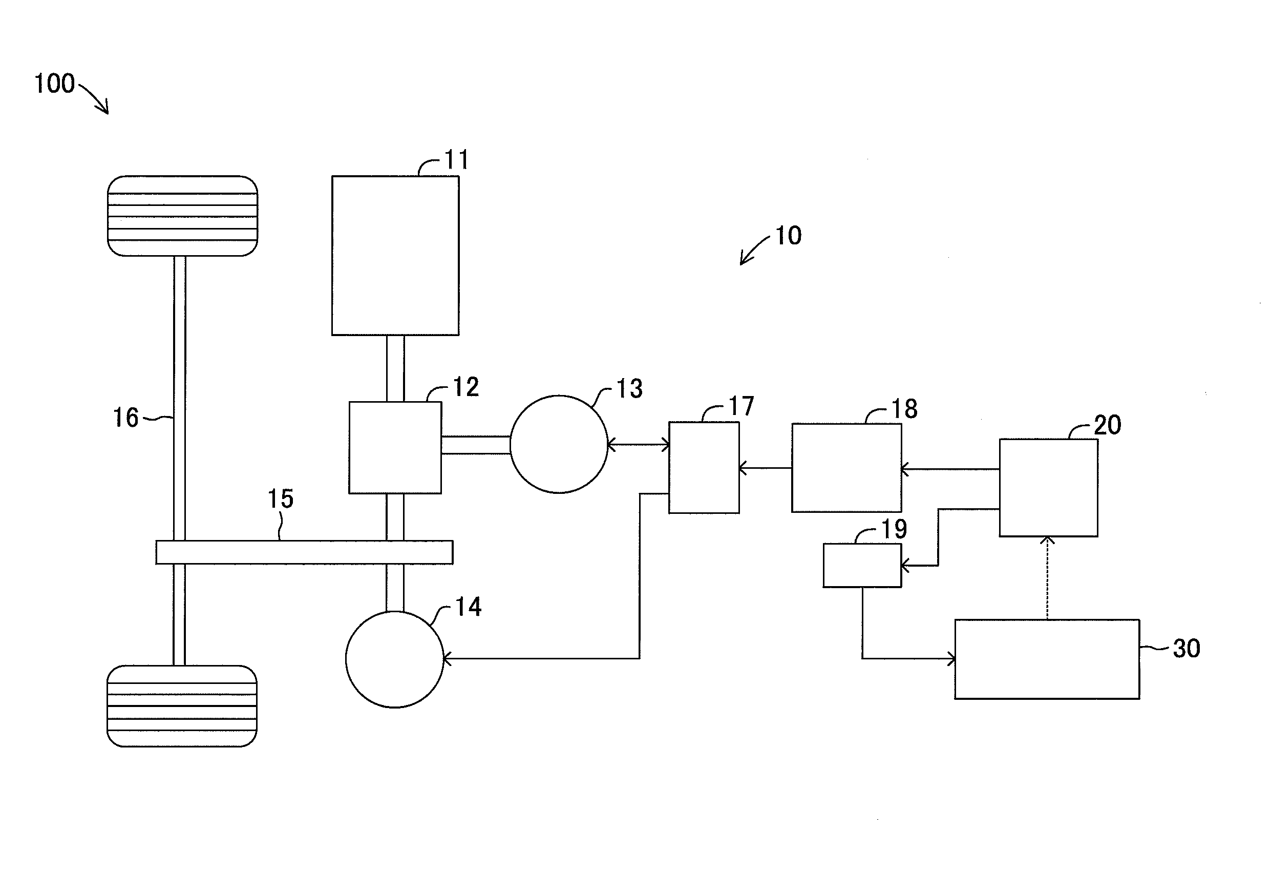
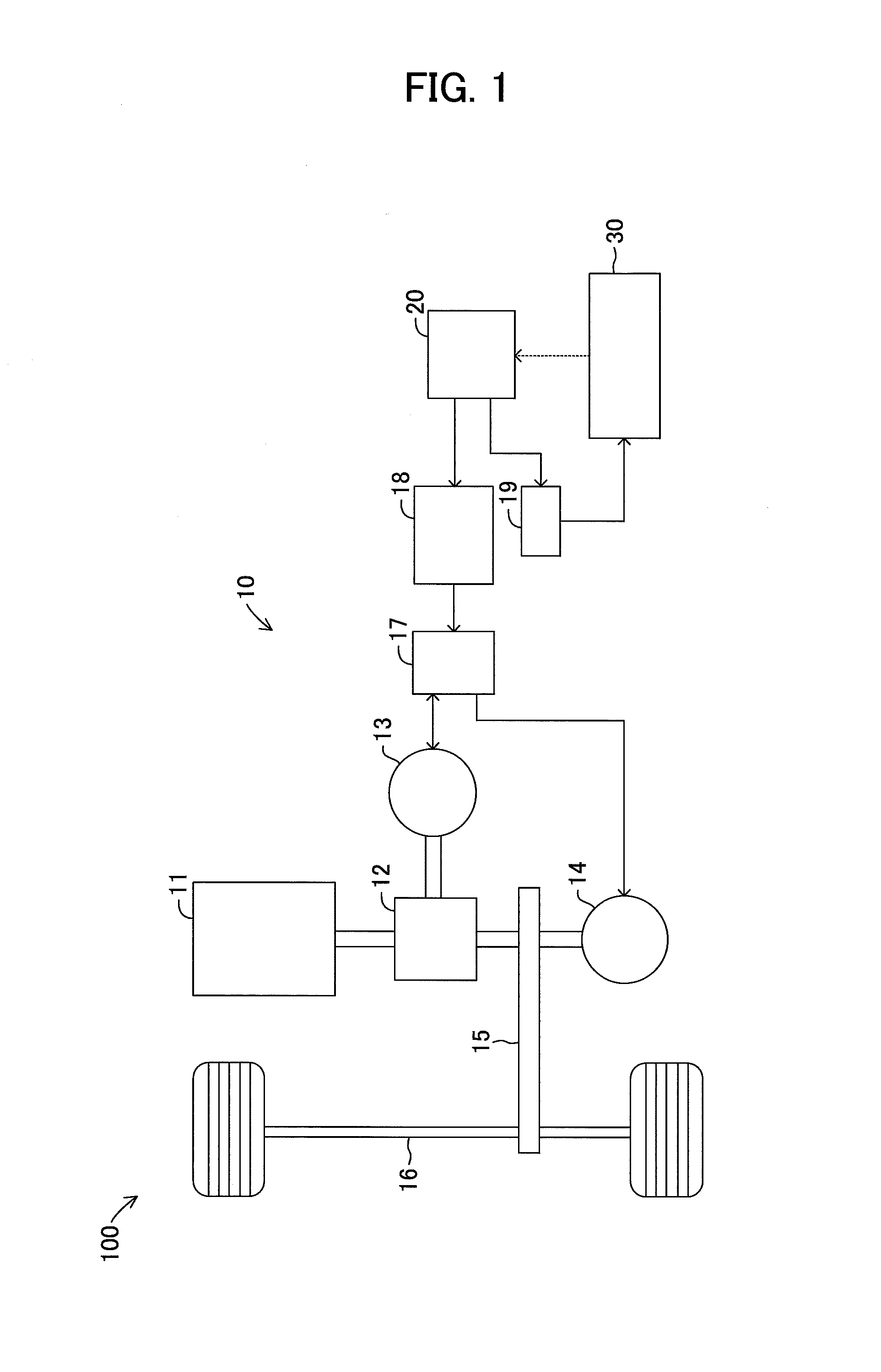
[0024]FIG. 1 is a block diagram for showing the configuration of a vehicle 100 to which the present device can be applied. Here, as the vehicle 100 to which the present device can be applied, for instance, an EV which comprises a motor generator as a generator motor driven by the electric power of a main battery as a main electric storage device mounted thereon and charges the main battery using a regeneration electric power and an external power supply which is supplied from a charging stand, etc., an HV which also comprises an engine in addition to an motor generator, and a PHV which can charge a main battery further using an external power supply in addition to an HV can be employed. In addition, in the present embodiment, a case where the vehicle 100 is a P...


PUM


Abstract

When the amount of charge of a temporary battery exceeds a predetermined amount of charge, a solar ECU31 constitutes a charge controller pumps up and boosts power stored in the battery collaborating with a solar charger of a power supply portion, and carries out pumping charge in a main electric storage. While the solar ECU31 carries out the pumping charge, the power supply portion solar charger supplies the generated power from an in-vehicle solar cell to solar ECU31 when the power generated by the in-vehicle solar cell is a predetermined power or less, and supplies the generated power from an in-vehicle solar cell to solar ECU31 and main battery when the power generated by the in-vehicle solar cell is larger than the predetermined power. Even where the pumping charge is being carried out, the power which the in-vehicle solar cell is continuously generating can be used without being discarded futilely.

Description

TECHNICAL FIELD[0001]The present invention relates to a charge control device which controls charging of a battery mounted on a vehicle using an in-vehicle solar cell.BACKGROUND ART[0002]In recent years, a charge control device which controls charging of a battery mounted on a vehicle using a solar cell (sunlight energy) has been proposed positively. For instance, in a controller of an electric vehicle disclosed in the following patent document 1 (PTL1), an electric power generated by a sunlight panel installed outside is supplied to an auxiliary battery which supplies an electric power to electrical apparatus inside the vehicle. And, this conventional controller boosts the electric power of an auxiliary battery and charges a main battery which supplies an electric power to a motor when the remaining capacity of the auxiliary battery reaches a predetermined value.CITATION LISTPatent Literature[0003][PTL1] Japanese Patent Application Laid-Open (kokai) No. 2012-75242SUMMARY OF INVENTI...

Claims


Application Information

Patent Timeline
IPC IPC(8): B60L11/18B60L50/15B60L50/16
CPCB60L11/1801B60L11/1861B60L11/1809H02J7/35B60L1/003B60L8/003B60L2210/14B60L2210/40B60L2220/14Y02T90/14Y02T10/7072B60L53/14B60L50/53B60L50/40B60L50/61B60L50/16B60L53/00B60L58/12B60L58/20B60L53/51Y02T10/62Y02T10/70Y02T10/72Y02T90/12B60K16/00
Inventor MAENO, SEIGEN
Owner TOYOTA JIDOSHA KK
Why Eureka
Try Eureka