
Driver customizable blind spot display method and apparatus

Active Publication Date: 2016-03-31
HYUNDAI MOTOR CO LTD
View PDF59 Cites 19 Cited by
  • Summary
  • Abstract
  • Description
  • Claims
  • Application Information

AI Technical Summary

Benefits of technology

The present invention provides a driver customizable blind spot display method and apparatus that can automatically adjust the angles of mirrors to correspond to the driver's eyes, allowing them to detect blind spots and recommend an optimal mirror angle setting to minimize them. This results in safer traveling as drivers can see what is behind them without having to look away from the road. The method includes calculating optimum mirror setting information based on the driver's eye positions and displaying a recommended blind spot coverage screen.

Problems solved by technology

These mirror angle adjustment methods, however, require manual driver operation, thus causing difficulty in accurate mirror angle adjustment and time required for mirror angle adjustment.
In addition, when a driver of a vehicle changes, the new driver is required to adjust angles of mirrors manually or remotely, increasing user inconvenience.
In addition, accurately adjusting angles of mirrors in a stationary state of vehicles increases adjustment difficult, and mirror angle adjustment during driving increases potential vehicle collisions.
However, there are no methods of the related art that allow drivers to view blind spots and viewable spots with their eyes via automatic mirror angle adjustment as described above.

Method used


Image

  • Driver customizable blind spot display method and apparatus
  • Driver customizable blind spot display method and apparatus
  • Driver customizable blind spot display method and apparatus

Examples


Embodiment Construction

[0037]It is understood that the term “vehicle” or “vehicular” or other similar term as used herein is inclusive of motor vehicles in general such as passenger automobiles including sports utility vehicles (SUV), buses, trucks, various commercial vehicles, watercraft including a variety of boats and ships, aircraft, and the like, and includes hybrid vehicles, electric vehicles, plug-in hybrid electric vehicles, hydrogen-powered vehicles and other alternative fuel vehicles (e.g., fuels derived from resources other than petroleum).

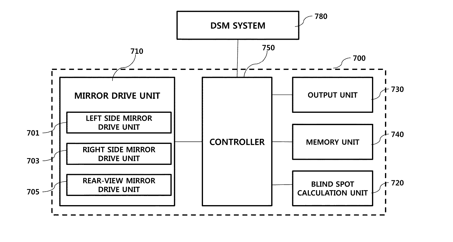
[0038]Although exemplary embodiments are described as using a plurality of units to perform the exemplary process, it is understood that the exemplary process may also be performed by one or a plurality of modules. Additionally, it is understood that the term controller / control unit refers to a hardware device that includes a memory and a process. The memory is configured to store the modules and the process is specifically configured to execute said modules ...


PUM


Abstract

A driver customizable blind spot display method and apparatus are provided. The method of displaying blind spots of a vehicle via a screen mounted within a vehicle includes receiving information regarding positions of the driver's eyes from a driver state monitoring system and receiving current mirror setting information on a per in-vehicle mirror basis from a mirror drive unit. Blind spots and viewable spots are then calculated using the information regarding positions of the driver's eyes and the current mirror setting information. Further, a current blind spot coverage screen is output that displays the calculated blind spots and viewable spots.

Description

CROSS REFERENCE TO RELATED APPLICATION(S)[0001]This application claims the benefit of Korean Patent Application No. 10-2014-0129097, filed on Sep. 26, 2014, which is hereby incorporated by reference as if fully set forth herein.BACKGROUND[0002]1. Field of the Invention[0003]The present invention relates to a driver customizable blind spot display method and apparatus and, more particularly, to a driver customizable blind spot display method and apparatus in which recommended mirror setting information for minimization of blind spots based on positions of the driver's eyes is calculated and automatically set and recommended mirror setting results are displayed on a screen, which enables a driver to directly view blind spots.[0004]2. Discussion of the Related Art[0005]Recent rapid development of information technology (IT) is exerting a great influence on the vehicle industry. Vehicle manufacturers are developing vehicle safety improvements and driver convenience by grafting various I...

Claims


Application Information

Patent Timeline
IPC IPC(8): B60R1/08
CPCB60R1/081B60R1/025
Inventor KIM, SAM, YONGKIM, JIN, KWONJUNG, HO, CHOULLEE, BYOUNG, JOON
Owner HYUNDAI MOTOR CO LTD
Learn More