Aircraft landing gear

Active Publication Date: 2016-03-31
SAFRAN LANDING SYST
View PDF4 Cites 3 Cited by
  • Summary
  • Abstract
  • Description
  • Claims
  • Application Information

AI Technical Summary

Benefits of technology

[0005]The object of the invention is to reduce the number of electrical cables incorporated in the systems associated with the landing gear and running to the landing gears.
[0006]In order to realize this aim, an aircraft landing gear is proposed comprising an axle intended to receive a wheel comprising a rim mounted to rotate on the axle by means of at least one rolling bearing, said rolling bearing comprising an inner ring mounted around the axle and an outer ring rotationally secured to the rim of the wheel, the landing gear further comprising measurement means intended to perform measurements of at least one operating parameter of the landing gear. According to the invention, the measurement means are incorporated in the

Problems solved by technology

In each of these architectures, a relatively large number of electrical cables stil

Method used


Image

  • Aircraft landing gear
  • Aircraft landing gear

Examples


Example

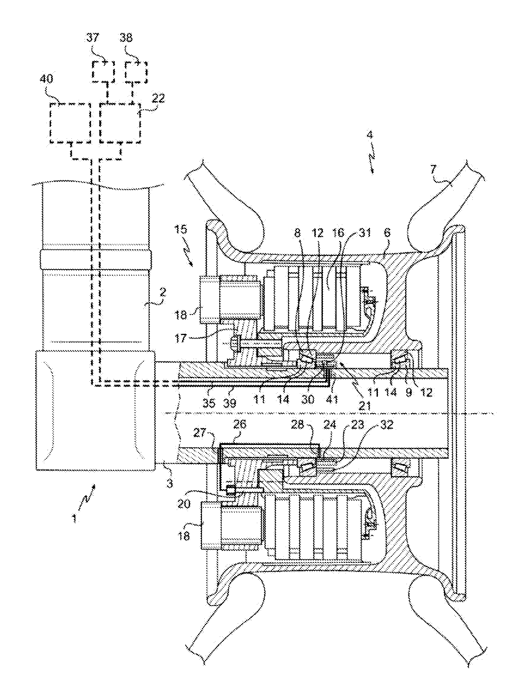
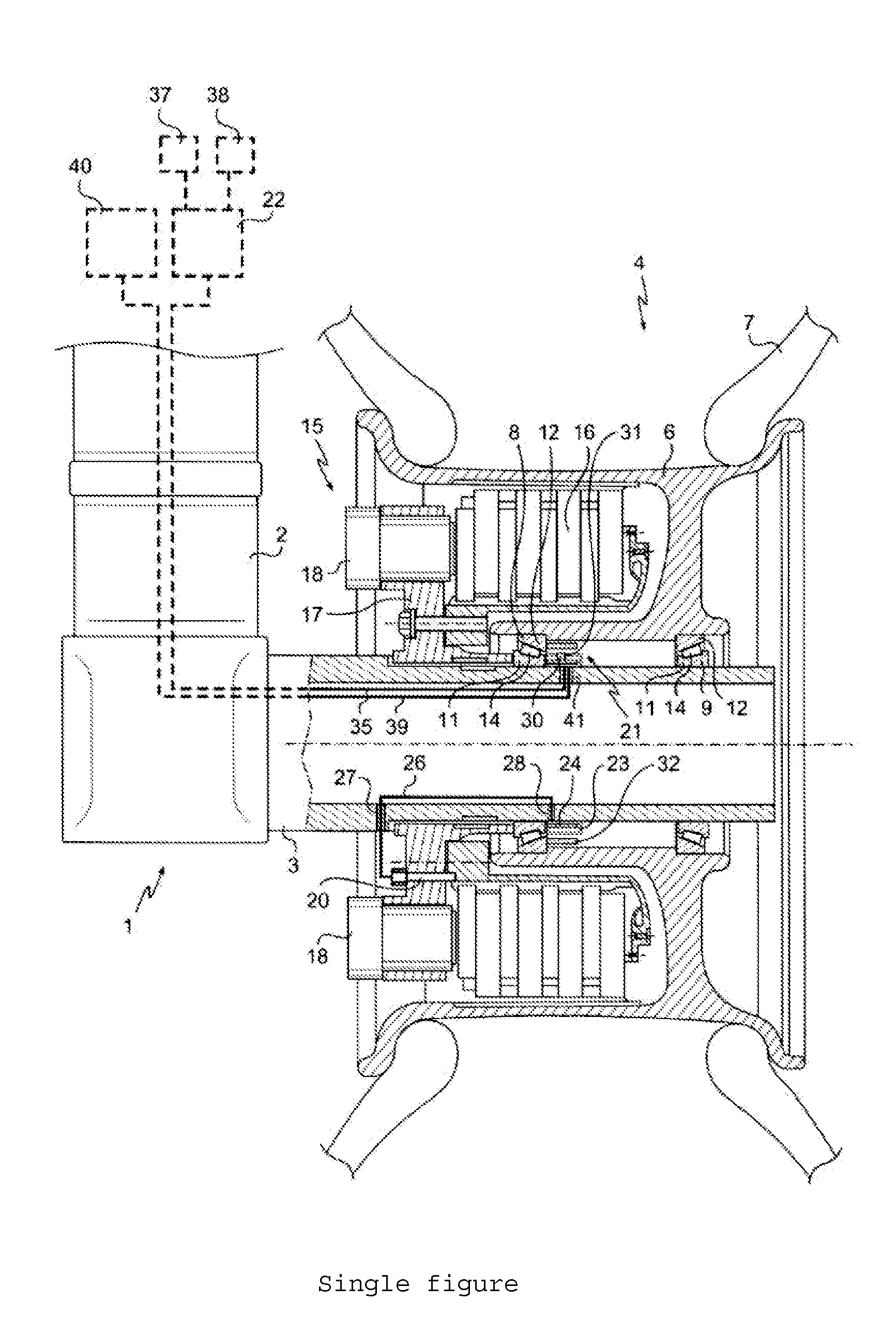
[0008]Referring to the single FIGURE, the landing gear 1 of the invention conventionally comprises a box structure articulated to the structure of an aircraft in which a sliding rod 2 is mounted to slide telescopically. The sliding rod 2 bears, at its end, an axle 3 intended to receive two wheels 4, only one of the wheels 4 being represented in the FIGURE to improve the readability of this FIGURE.

[0009]The wheel 4 comprises a rim 6 which bears a tyre 7 and which is mounted to rotate on the axle 3 by means of an inner tapered rolling bearing 8 and an outer tapered rolling bearing 9. Each of these tapered rolling bearings 8, 9 comprises an inner ring 11 mounted around the axle 3, an outer ring 12 rotationally secured to the rim 6 of the wheel 4, a cage and tapered rollers 14.

[0010]The wheel 4 is further equipped with a brake 15 suitable for braking the wheel, the brake 15 comprising a stack of carbon discs 16 extending into the rim 6 of the wheel 4, a crown ring 17 fixed onto the axle...


PUM


Abstract

An aircraft landing gear comprising an axle (3) intended to receive a wheel (4) comprising a rim (6) mounted to rotate on the axle (3) by means of at least one rolling bearing (8). The rolling bearing (8) comprises an inner ring (11) mounted around the axle (3) and an outer ring (12) rotationally secured to the rim (6) of the wheel (4). The landing gear further comprising a measurement device (21) intended to perform measurements of at least one operating parameter of the landing gear. The measurement device (21) is incorporated in the rolling bearing (8) by being secured to one of the inner or outer rings of the rolling bearing (8).

Description

BACKGROUND OF THE INVENTION[0001]The avionics systems of modern aircraft are increasingly less “centralized” and increasingly more “distributed”.[0002]Thus, centralized architectures, comprising a relatively complex central computer connected by multiple electrical cables to actuators that it drives or to sensors that supply it with measurement data, are being replaced by distributed architectures comprising a certain number of “remote” computers situated in proximity to the actuators and the sensors. These remote computers are possibly linked to a computation-dedicated “core” computer.[0003]The splitting up of the central computer into a plurality of remote computers makes it possible to reduce the weight of the aircraft through the simplification of the wiring, and to reduce the cost of the avionics systems, notably by virtue of the fact that the remote computers and the core computer are now designed to be generic computers that can be incorporated in different systems. This spli...

Claims


Application Information

Patent Timeline
IPC IPC(8): B64C25/34B64D43/00G01P3/36G01P3/44
CPCB64C25/34G01P3/36G01P3/44B64D43/00B64C25/36B60T8/329F16C41/007F16C19/386F16C19/548F16C2326/02B60T8/00F16C41/00
Inventor ZABULON, JOELFRANK, DAVID
Owner SAFRAN LANDING SYST
Why Eureka
Try Eureka