Turbocharger Variable-Vane Cartridge With Nozzle Ring and Pipe Secured By Two-Piece Self-Centering Spacers

Inactive Publication Date: 2016-03-31
GARRETT TRANSPORATION I INC
View PDF6 Cites 14 Cited by
  • Summary
  • Abstract
  • Description
  • Claims
  • Application Information

AI Technical Summary

Benefits of technology

[0016]In one embodiment, the conical countersinks are defined in the face of the nozzle ring and the first ends of the sleeves define the conical surfaces that engage in the countersinks. It i

Problems solved by technology

In those prior-art arrangements, cracking was seen in the region of the

Method used


Image

  • Turbocharger Variable-Vane Cartridge With Nozzle Ring and Pipe Secured By Two-Piece Self-Centering Spacers
  • Turbocharger Variable-Vane Cartridge With Nozzle Ring and Pipe Secured By Two-Piece Self-Centering Spacers
  • Turbocharger Variable-Vane Cartridge With Nozzle Ring and Pipe Secured By Two-Piece Self-Centering Spacers

Examples


Example

DETAILED DESCRIPTION OF THE DRAWINGS

[0025]The present inventions now will be described more fully hereinafter with reference to the accompanying drawings, in which some but not all embodiments of the inventions are shown. Indeed, these inventions may be embodied in many different forms and should not be construed as limited to the embodiments set forth herein; rather, these embodiments are provided so that this disclosure will satisfy applicable legal requirements. Like numbers refer to like elements throughout.

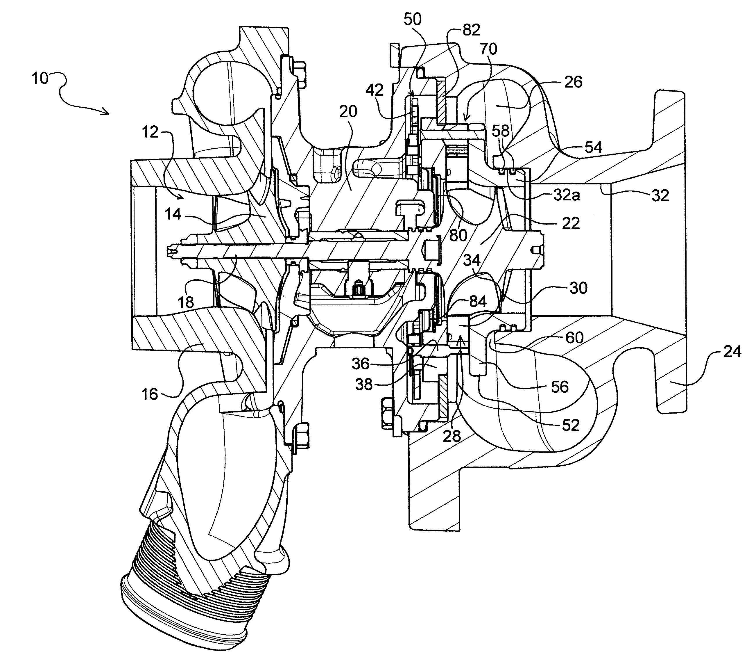
[0026]A turbocharger 10 in accordance with one embodiment of the invention is illustrated in cross-sectional view in FIG. 1. The turbocharger comprises a compressor 12 having a compressor wheel or impeller 14 mounted in a compressor housing 16 on one end of a rotatable shaft 18. The shaft is supported in bearings (not specifically illustrated) mounted in a center housing 20 of the turbocharger. The shaft 18 is rotated by a turbine wheel 22 mounted on the other end of the shaf...


PUM


Abstract

A variable-nozzle turbocharger includes a variable vane mechanism that has an annular nozzle ring supporting an array of rotatable vanes, an insert having a tubular portion sealingly received into a bore of the turbine housing and having a nozzle portion extending radially out from one end of the tubular portion and being axially spaced from the nozzle ring with the vanes therebetween, and a plurality of two-piece self-centering spacer assemblies connected between the nozzle portion of the insert and the nozzle ring. Each spacer assembly comprises a tubular sleeve and a separate pin that passes through the through-passage of the sleeve, end portions of the pin being secured respectively to the nozzle ring and the nozzle portion. One end of each sleeve has a conical surface and engages in a corresponding conical countersink in the adjacent face of the nozzle ring or nozzle portion.

Description

BACKGROUND OF THE INVENTION[0001]The present invention relates to turbochargers having a variable-nozzle turbine in which an array of movable vanes is disposed in the nozzle of the turbine for regulating exhaust gas flow into the turbine.[0002]An exhaust gas-driven turbocharger is a device used in conjunction with an internal combustion engine for increasing the power output of the engine by compressing the air that is delivered to the air intake of the engine to be mixed with fuel and burned in the engine. A turbocharger comprises a compressor wheel mounted on one end of a shaft in a compressor housing and a turbine wheel mounted on the other end of the shaft in a turbine housing. Typically the turbine housing is foamed separately from the compressor housing, and there is yet another center housing connected between the turbine and compressor housings for containing bearings for the shaft. The turbine housing defines a generally annular chamber that surrounds the turbine wheel and ...

Claims


Application Information

Patent Timeline
IPC IPC(8): F02C6/12F01D17/16
CPCF01D17/16F05D2220/40F02C6/12F01D9/048F01D17/165F02B37/24F05D2230/642F05D2260/30F05D2260/31F05D2250/51
Inventor BARTHELET, PIERREMORAND, NICOLASSEVERIN, EMMANUELBELTRAMI, CALOGEROEUMONT, VINCENTABEL, FRANCISGERARD, ARNAUDTINGAUD, AURELIENKRISHNAMOORTHY, JAYAVENKATESHWARAN
Owner GARRETT TRANSPORATION I INC
Why Eureka
Try Eureka