Touch panel system and electronic device

a technology of electronic devices and touch panels, applied in the direction of generating/distributing signals, instruments, computing, etc., can solve the problem of not being able to remove an erroneous signal

Active Publication Date: 2016-03-31
SHARP KK
View PDF0 Cites 18 Cited by
  • Summary
  • Abstract
  • Description
  • Claims
  • Application Information

AI Technical Summary

Benefits of technology

[0017]According to the aspects of the present invention, the effect of providing a touch panel system and an electronic device capable of appropriately detecting a synchronization signal is accomplished.

Problems solved by technology

The touch panel system disclosed in PTL 1 has a problem in that it is not possible to remove an erroneous signal that is generated by electromagnetic noise which is caused by the touch of a hand, a finger, and the like of a human body, which receives electromagnetic noise when touching the electronic pen, on a touch panel and which is generated at a position different from the position of the touch.

Method used


Image

  • Touch panel system and electronic device
  • Touch panel system and electronic device
  • Touch panel system and electronic device

Examples


first embodiment

[0041]An embodiment of the present invention will be described as follows on the basis of FIG. 1 to FIG. 14.

(Configuration of Touch Panel System)

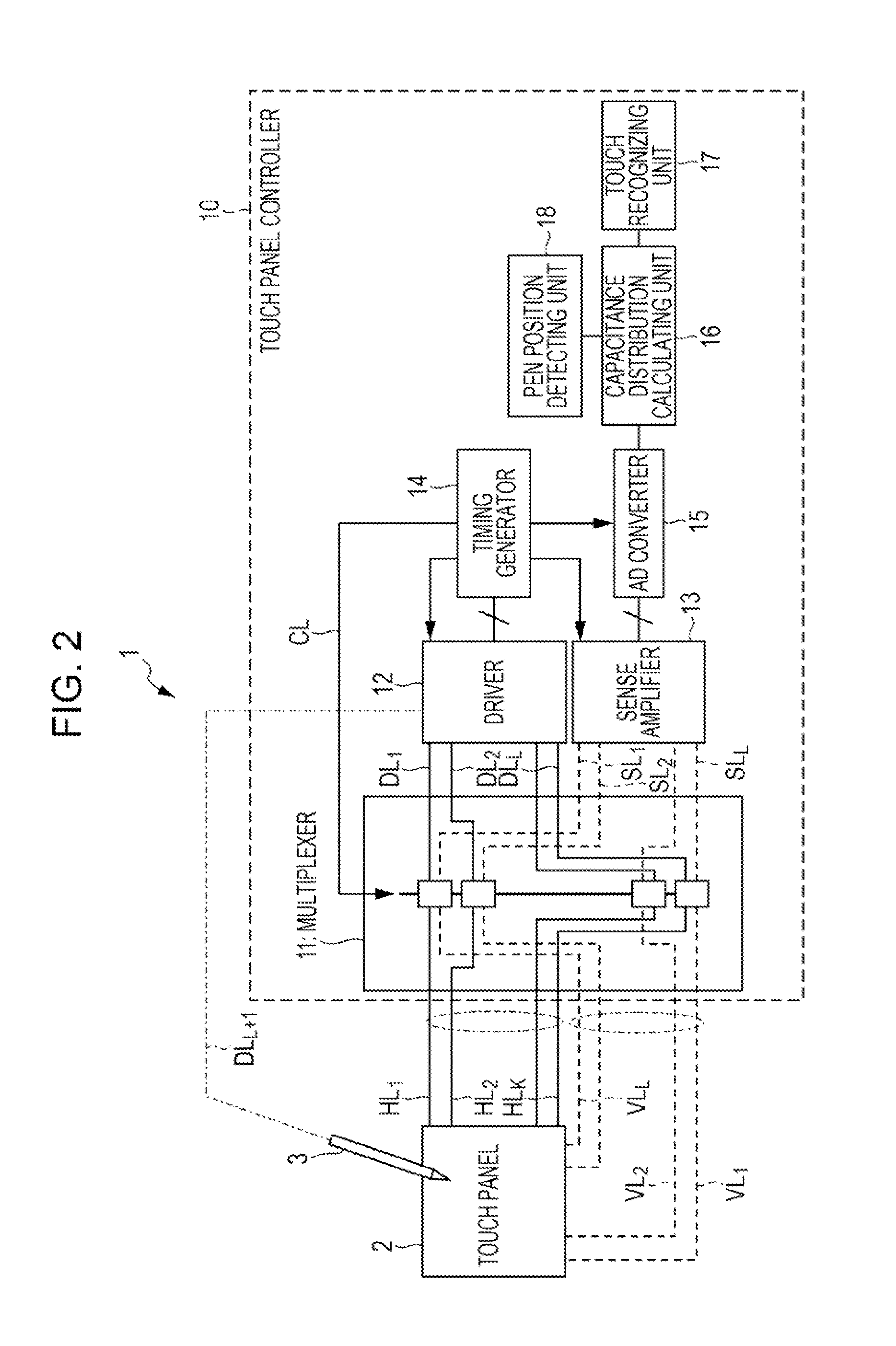
[0042]A configuration of a touch panel system 1 of the present embodiment will be described on the basis of FIG. 2 and FIG. 3. FIG. 2 is a block diagram illustrating a configuration of the touch panel system 1 of the present embodiment, and FIG. 3 is an interconnect diagram illustrating a configuration of a touch panel disposed in the touch panel system.

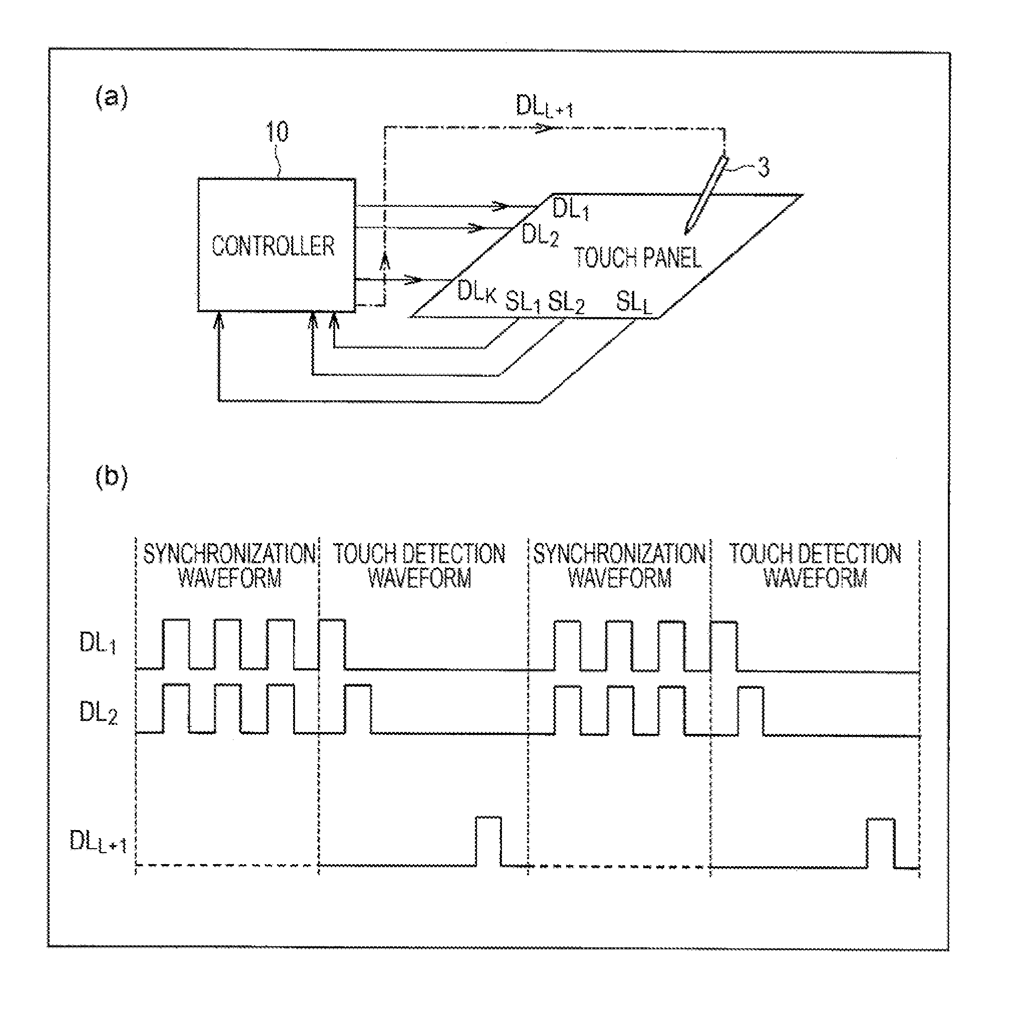
[0043]The touch panel system 1 of the present embodiment, as illustrated in FIG. 2, is provided with a touch panel 2, a stylus pen 3 as a touch pen and an electronic pen, and a touch panel controller 10 that drives the touch panel 2 and the stylus pen 3.

[0044]The touch panel 2, as illustrated in FIG. 3, is provided with horizontal signal lines HL1 to HLK as K (K is a positive integer) numbers of first signal lines that are plural lines arranged parallel to each other along the horizontal dir...

second embodiment

[0140]Another embodiment of the present invention will be described as follows on the basis of FIG. 15(a) to FIG. 21. Configurations other than those described in the present embodiment are the same as those of the first embodiment. For convenience of description, members having the same function as the members illustrated in the drawings of the first embodiment will be designated by the same reference sign, and descriptions thereof will be omitted.

(Characteristic Operation of Synchronization of Touch Panel Controller and Stylus Pen)

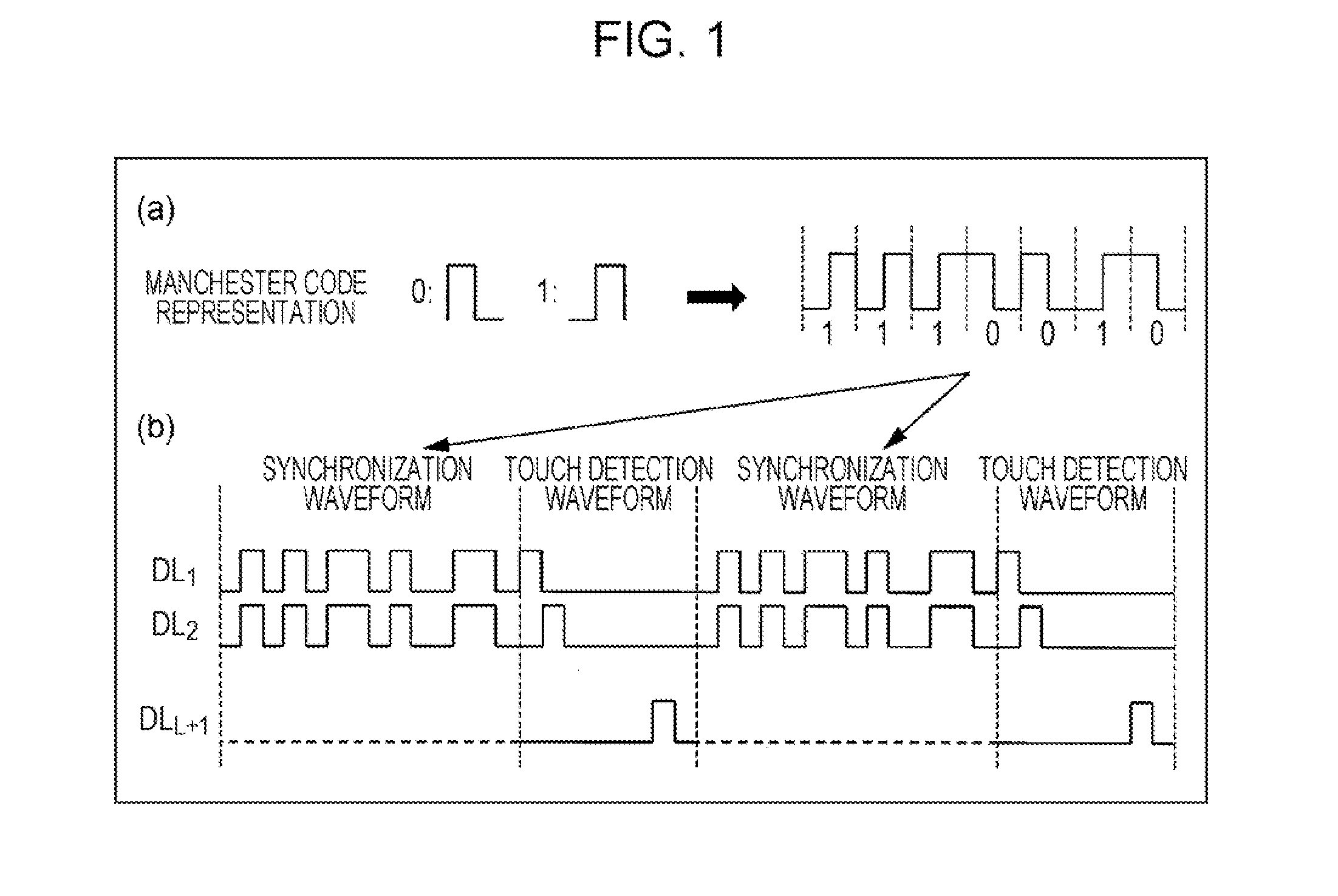
[0141]In the present embodiment, synchronization of the stylus pen 3 and, furthermore, a method that may prevent the pulses of the dedicated synchronization signal from not being captured will be described on the basis of FIG. 15(a) to FIG. 19(c). FIG. 15(a) is a waveform diagram illustrating the input waveform of a signal received by the stylus pen in the touch panel system of the present embodiment, and FIG. 15(b) is a waveform diagram illustrating an ...

third embodiment

[0161]Still another embodiment of the present invention will be described as follows on the basis of FIG. 22. Configurations other than those described in the present embodiment are the same as those of the first embodiment. For convenience of description, members having the same function as the members illustrated in the drawings of the first embodiment will be designated by the same reference sign, and descriptions thereof will be omitted.

[0162]The touch panel system 1 of the first embodiment is described in an example where one stylus pen 3 is disposed. However, the touch panel system 1 of the present embodiment is different in that two stylus pens 3A and 3B can be used as the stylus pen 3.

[0163]In the touch panel system 1 of the present embodiment, the two stylus pens 3A and 3B are disposed as the stylus pen 3 as illustrated in FIG. 22.

[0164]While the stylus pen 3A drives the pen tip portion 31 with a waveform corresponding to the drive line DLL+1, the stylus pen 3B drives the p...


PUM


Abstract

In a touch panel system of the present invention, a touch pen is configured of an electronic pen that signals can be input into and output from. A touch panel controller includes a synchronization signal transmission unit that transmits a synchronization signal to the electronic pen during synchronization signal transmission periods immediately before each of a first signal line drive period and a second signal line drive period. The synchronization signal transmission unit transmits the synchronization signal of which the waveform is configured of a Manchester-coded pseudorandom sequence having periodicity to the electronic pen during the synchronization signal transmission period. The electronic pen includes a synchronization signal detecting unit that detects the synchronization signal.

Description

TECHNICAL FIELD[0001]The present invention relates to a touch panel system and an electronic device that detect the position of the touch of a touch pen on a touch panel which has electrostatic capacitances formed at each intersection of a plurality of first signal lines and a plurality of second signal lines. Specifically, the present invention relates to the synchronization of a touch pen and a touch panel controller.BACKGROUND ART[0002]In the related art, there is known, for example, a touch panel system disclosed in PTL 1 as a touch panel system that detects the position of the touch of a touch pen on a touch panel which has electrostatic capacitances formed at each intersection of a plurality of first signal lines and a plurality of second signal lines.[0003]The touch panel system disclosed in PTL 1 includes a plurality of electronic pens, a panel main body that includes a touch face on which a touch operation is performed by the electronic pens and a finger and in which a plur...

Claims


Application Information

Patent Timeline
Patent Type & Authority Applications(United States)
IPC IPC(8): G06F1/12G06F1/24G06F3/0354G06F3/038G06F3/041G06F3/044
CPCG06F1/12G06F3/0416G06F1/24G06F3/03545G06F3/038G06F3/044G06F3/03G06F3/0383G06F3/04166G06F3/0441G06F3/0446
Inventor TAKEDA, MICHIAKITAKAYA, MAMORU
Owner SHARP KK
Why Eureka
Try Eureka