Fuel cell and manufacturing method of fuel cell

Active Publication Date: 2016-03-31
TOYOTA JIDOSHA KK
View PDF9 Cites 3 Cited by
  • Summary
  • Abstract
  • Description
  • Claims
  • Application Information

AI Technical Summary

Benefits of technology

[0009]Another aspect of the invention also relates to a fuel cell. This fuel cell includes a membrane electrode assembly; a porous member that has a first surface, a second surface, and an end surface portion, the first surface and the second surface being on opposite sides of the porous member, the first surface being arranged on a cathode side of the membrane electrode assembly, the end surface portion being between an end side portion of the first surface and an end side portion of the second surface; a sealing plate arranged along the end side portion of the first surface: and a separator plate arranged on the second surface, wherein the porous member is configured to supply oxidant gas to the membrane electrode assembly through the first surface, and discharge oxidant off-gas to a discharge portion of the fuel cell vi

Problems solved by technology

When water remains in this portion, power generating performance may decrea

Method used


Image

  • Fuel cell and manufacturing method of fuel cell
  • Fuel cell and manufacturing method of fuel cell
  • Fuel cell and manufacturing method of fuel cell

Examples


Embodiment Construction

[0029]Hereinafter, a first example embodiment of the invention will be described.

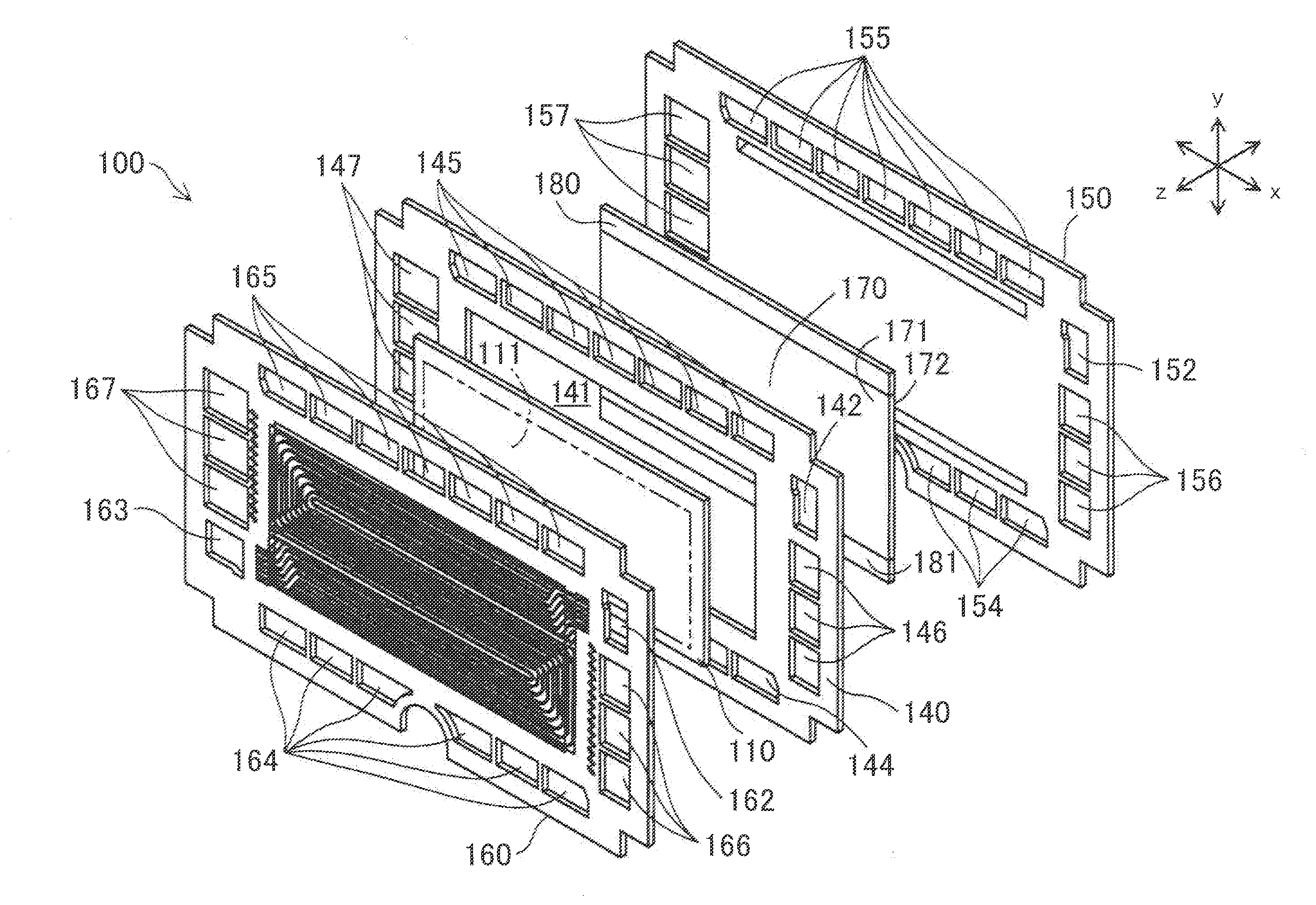
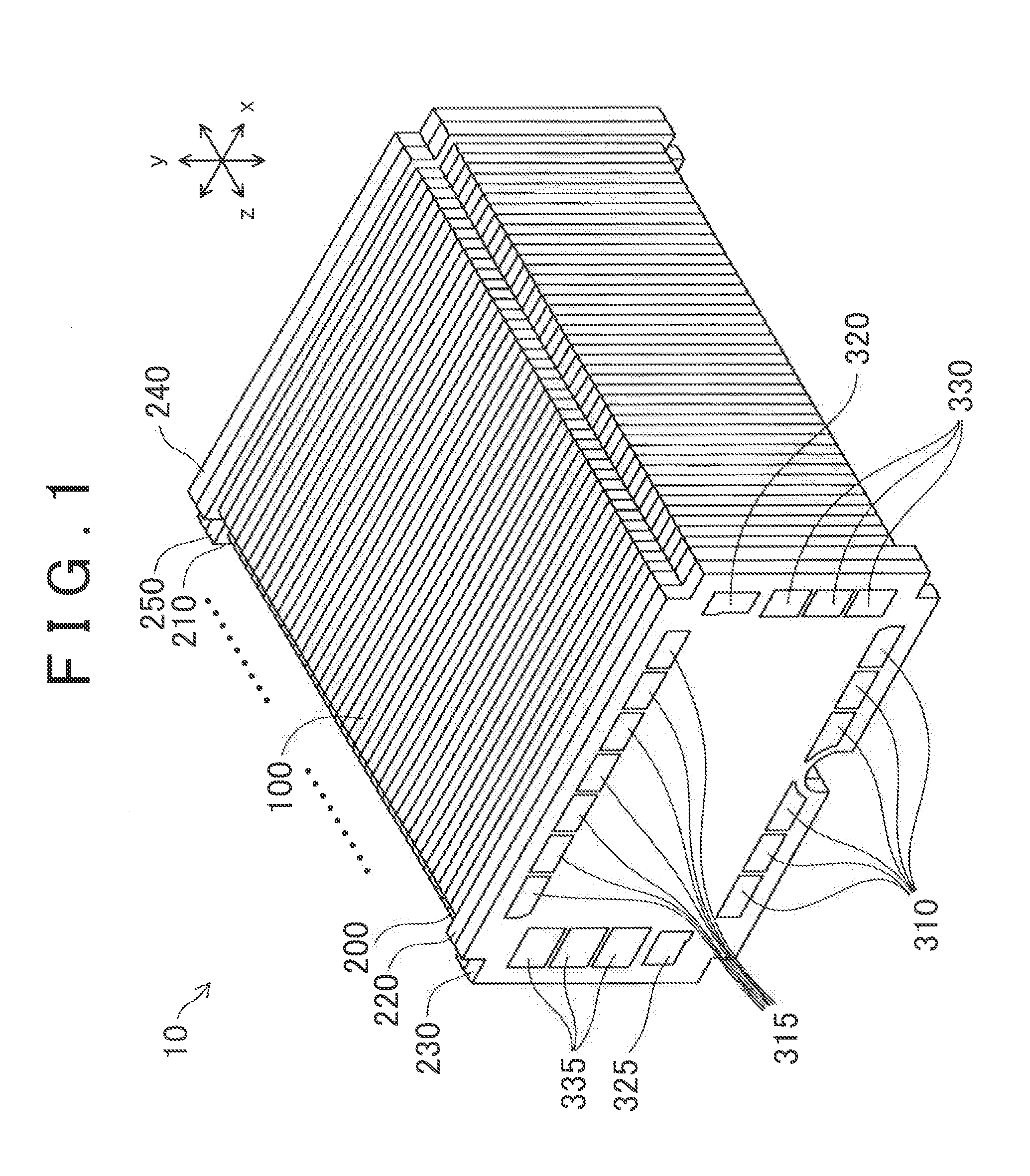
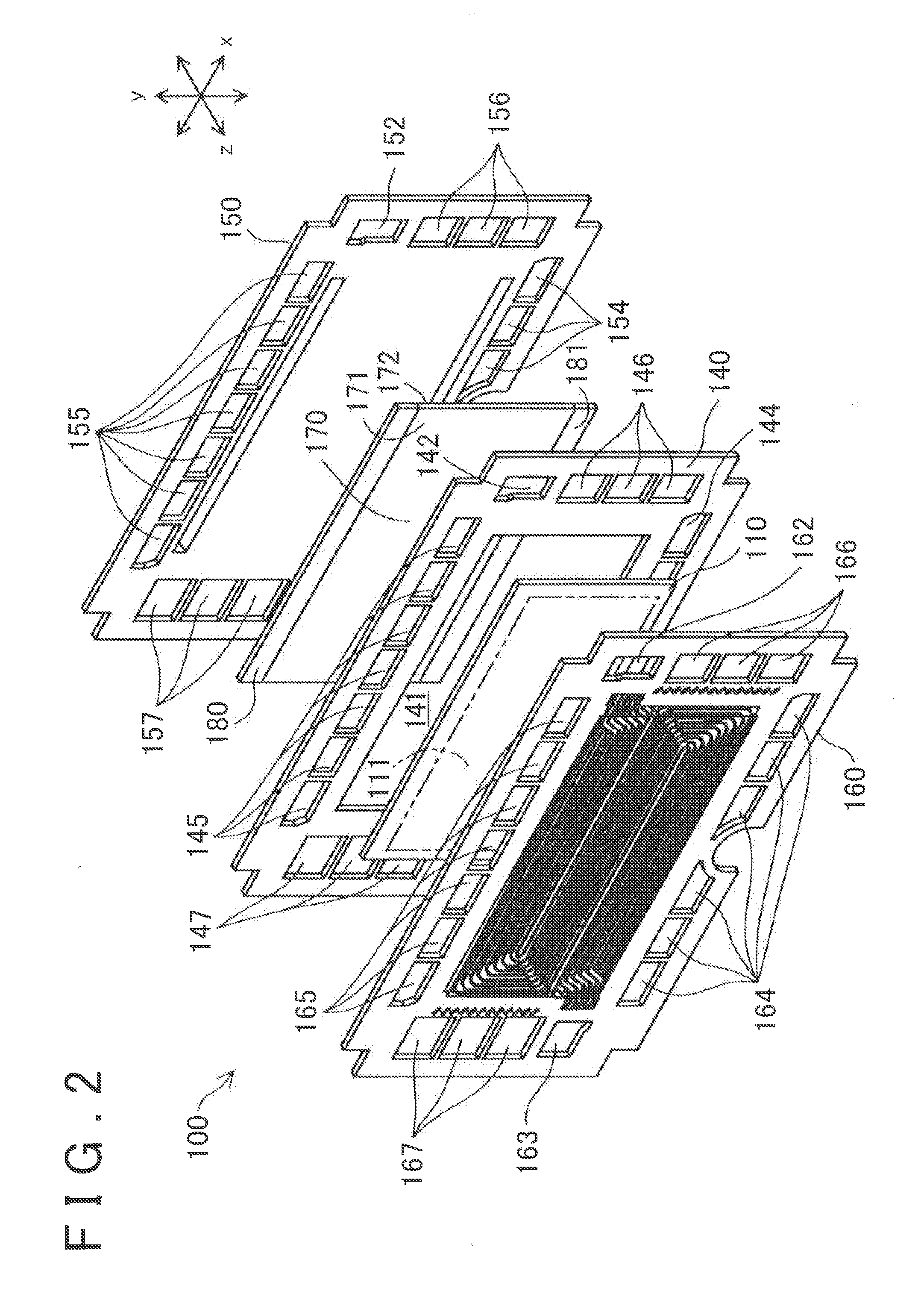
[0030]FIG. 1 is a perspective view schematically showing the structure of a fuel cell 10 according to the first example embodiment. The fuel cell 10 has a stacked structure in which a plurality of unit ceils 100 of the fuel cell 10 are stacked together in a Z direction (hereinafter also referred to as the “stacking direction”), and sandwiched between a pair of end plates 230 and 240. In the fuel cell 10, an insulating plate 220 and a terminal plate 200 are arranged between the end plate 230 on the front end side and the unit cells 100, and an insulating plate 250 and a terminal plate 210 are arranged between the end plate 240 on the rear end side and the unit cells 100. The terminal plates 200 and 210 are collector plates for collecting power generated by the unit cells 100, and output the power collected from terminals, not shown, to an external device. The unit cells 100, the terminal plates 200 and 2...


PUM


Abstract

A fuel cell includes: a membrane electrode assembly; a porous member arranged on a cathode side of the membrane electrode assembly and having a first surface, a second surface, and an end surface portion, the end surface portion being between an end side portion of the first surface and the second surface; a sealing plate arranged along the end side portion of the first surface; and a separator plate arranged on the second surface. The porous member supplies oxidant gas to the membrane electrode assembly through the first surface, and discharges oxidant off-gas to a discharge portion of the fuel ceil via the end surface portion. The first surface has a first region facing the sealing plate and being between the sealing plate and the second region, the second surface has a second region. A hydrophilicity of the first region is different from that of the second region.

Description

INCORPORATION BY REFERENCE[0001]The disclosure of Japanese Patent Application No. 2014-194930 filed on Sep. 25, 2014 including the specification, drawings and abstract is incorporated herein by reference in its entirety.BACKGROUND OF THE. INVENTION[0002]1. Field of the Invention[0003]The invention relates to a fuel cell and a manufacturing method of a fuel cell.[0004]2. Description of Related Art[0005]Japanese Patent Application Publication No. 2012-123949 (JP 2012-123949 A) describes a fuel cell that includes a porous member that forms a flow path to supply oxidant gas to a membrane electrode assembly, a sealing plate chat is arranged on one surface of the porous member, and a separator plate that is arranged on the other surface of the porous member. This fuel cell discharges water produced as a result of generating power, outside the fuel cell via the flow path formed by the porous member,[0006]However, in the flow path formed by the porous member, water may remain in a portion o...

Claims


Application Information

Patent Timeline
IPC IPC(8): H01M8/02
CPCH01M8/0273H01M8/0276H01M8/0247H01M8/00H01M8/02H01M8/06H01M8/023Y02P70/50Y02E60/50
Inventor YOSHIZUMI, TOMOOKONDOU, TAKASHI
Owner TOYOTA JIDOSHA KK
Why Eureka
Try Eureka