
Antifouling coating, heat exchanger provided with same, and method for manufacturing heat exchanger

Active Publication Date: 2015-08-27
MITSUBISHI ELECTRIC CORP
View PDF4 Cites 1 Cited by
  • Summary
  • Abstract
  • Description
  • Claims
  • Application Information

AI Technical Summary

Benefits of technology

The present invention provides an antifouling coating that has high hydrophilicity, antifouling ability, and resistance to adhesion of contaminants and degradation even in the presence of metal particles. Additionally, the coating maintains antifouling performance and hydrophilicity in a heat exchanger with a fin, preventing corrosion even in an environment with a large amount of contaminating substances.

Problems solved by technology

Surfaces of various products can look dirty, cause sanitary problems, or demonstrate performance degradation caused by corrosion or the like, due to exposure to various contaminating substances from the environment.
Among such products, heat exchangers in air conditioning equipment are highly susceptible to contamination from the environment due to the functions thereof, and the contamination easily causes a variety of failures.
However, when an inorganic hydrophilic coating contains a large amount of an inorganic component such as water glass or boehmite, the coating easily adsorbs odor.
Meanwhile, organic components of organic hydrophilic coatings are easily decomposed, degraded, or dissolved in condensed water with the passage of time, and the antifouling performance or hydrophilicity of the hydrophilic coating are degraded.

Method used


Image

  • Antifouling coating, heat exchanger provided with same, and method for manufacturing heat exchanger
  • Antifouling coating, heat exchanger provided with same, and method for manufacturing heat exchanger
  • Antifouling coating, heat exchanger provided with same, and method for manufacturing heat exchanger

Examples


embodiment 1

[0021]At metal processing (welding, cutting, etc.) sites, enterprises where metal dust is handled, vehicles such as railway vehicles, and related facilities, metal particles such as particles of iron, copper, zinc, or alloys thereof, and particles to which such metal particles have adhered float in the air (such particles will be together referred to hereinbelow as “metal particles”). A coating constituted by an inorganic material, an organic material, or a combination thereof, in particular highly hydrophilic coating having a large number of polar groups, such as hydroxyl groups, on the surface, is degraded by adhesion of the metal particles, or the metal particles are easily firmly attached thereto.

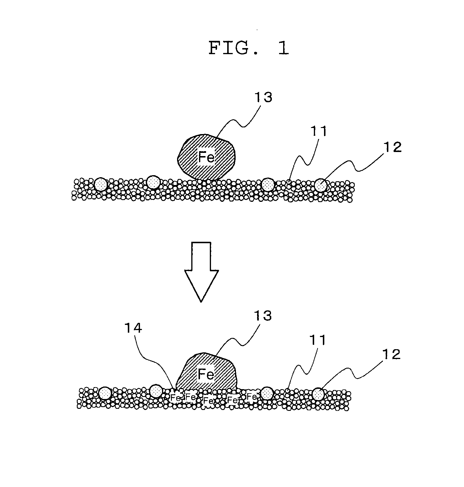
[0022]FIG. 1 is a schematic diagram illustrating the degradation of the conventional coating caused by adhesion of metal particles. In the conventional coating depicted in FIG. 1, ultrafine silica particles 11 serving as fine inorganic particles are aggregated and fluororesin particles ...

embodiment 2

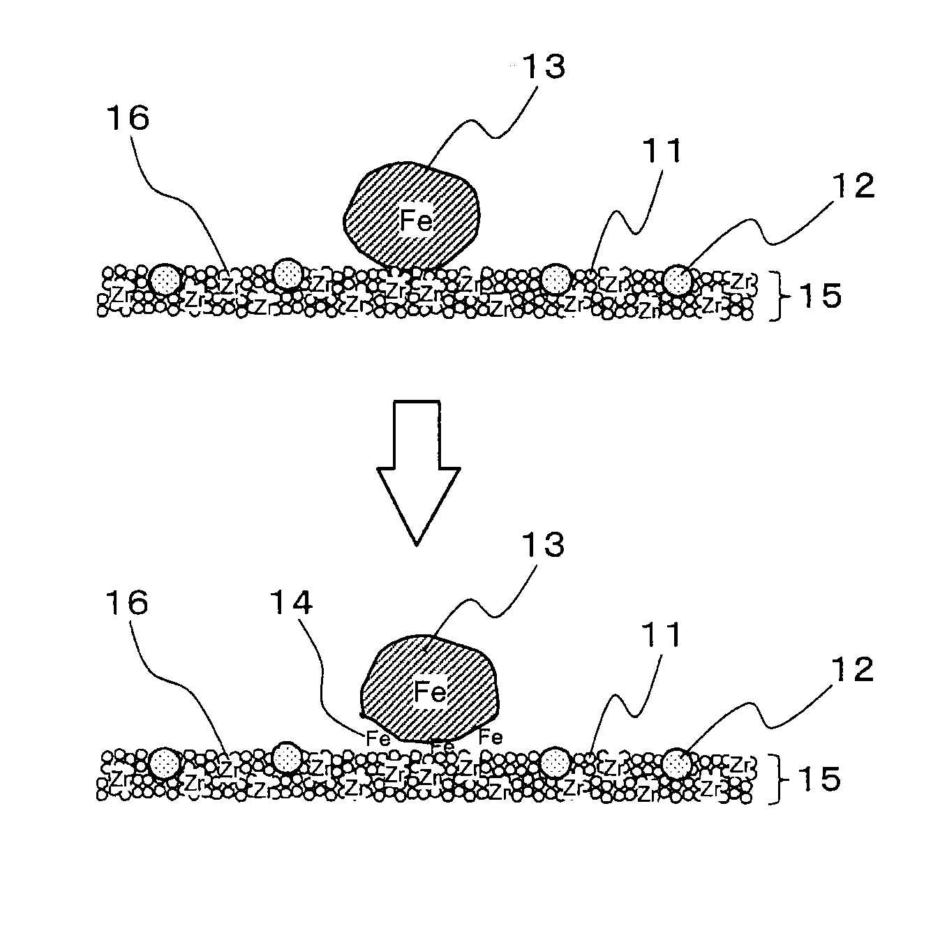
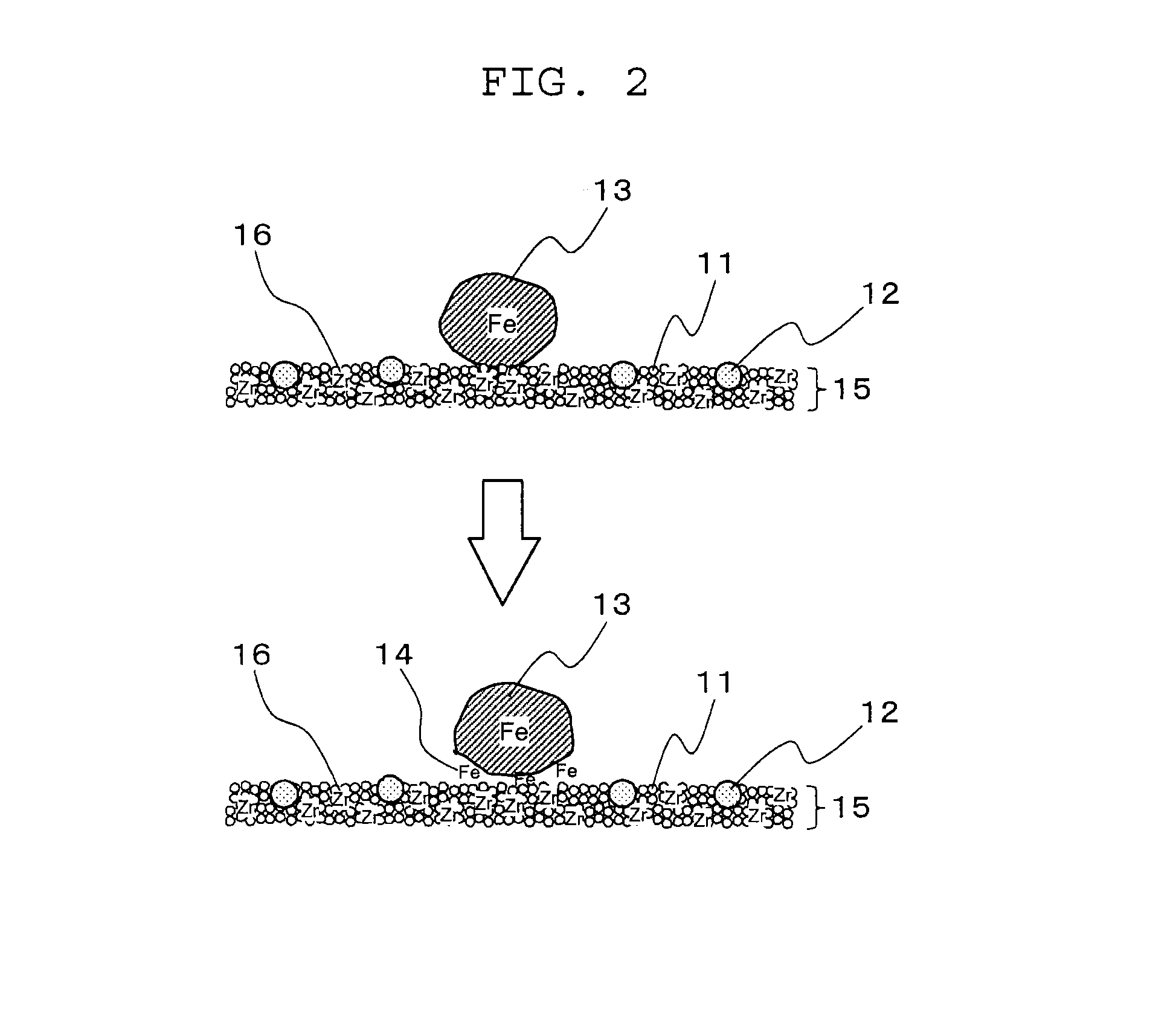
[0036]The antifouling coating according to Embodiment 2 of the present invention has a hydrophilic organic coating as a primary layer for an inorganic coating. Where the antifouling coating of such a form is used in a heat exchanger, good heat exchanger characteristics are obtained. As a result of forming a hydrophilic organic coating as a primary layer on the surface of a heat exchanger, for example, the surface of fins, forming a reaction layer from an aqueous solution comprising a zirconium compound which is at least one selected from zirconium chloride and zirconyl chloride on the hydrophilic organic coating, and forming an inorganic coating from a water-based coating composition comprising ultrafine silica particles on the reaction layer, or forming an inorganic coating from a water-based coating composition comprising ultrafine silica particles and a zirconium compound which is at least one selected from zirconium chloride and zirconyl chloride, it is possible to inhibit the c...

example 1

[0052]A water-based coating composition having the composition shown in Table 1 was prepared by stirring and mixing pure water, colloidal silica (Snowtex OXS manufactured by Nissan Kagaku Kogyo KK) comprising ultrafine silica particles with an average particle size of 6 nm, a PTFE dispersion with an average particle size of 150 nm, and zirconium chloride (12% by mass of the ultrafine silica particles), adding a nonionic surfactant (polyoxyethylene lauryl alkyl ester) at 0.1% by mass to the mixture, and further stirring and mixing.

[0053]The obtained water-based coating composition was coated on an aluminum fin material and dried with an air blower. The aluminum fin material with the coating formed thereon was wetted by dipping it into water, an iron powder with an average particle size of 45 μm was blown thereon, followed by drying with an air blower, and the adhesion state of the iron powder was observed. The adhesion state of the iron powder was visually evaluated. The evaluation u...


PUM

PropertyMeasurementUnit
Percent by massaaaaaaaaaa

Abstract

The present invention provides an antifouling coating formed from a water-based coating composition comprising 0.1% by mass to 10% by mass of ultrafine silica particles having an average particle size equal to or less than 25 nm, 5% by mass to 50% by mass, relative to the ultrafine silica particles, of a zirconium compound which is at least one selected from zirconium chloride and zirconyl chloride, and 30% by mass to 99.5% by mass of water. In accordance with the present invention, it is possible to provide an antifouling coating that can maintain the antifouling performance and hydrophilicity and prevent corrosion of fins even under an environment with a large amount of contaminating substances, such as metal particles, in the air.

Description

TECHNICAL FIELD[0001]The present invention relates to an antifouling coating that can prevent adhesion of contamination to a surface, and to a heat exchanger provided with the coating. More particularly, the present invention relates to an antifouling coating for use in metal processing (welding, cutting, etc.) sites, enterprises where metal dust is handled, vehicles such as railway vehicles, and related facilities, and also to heat exchangers for air conditioners.BACKGROUND ART[0002]Surfaces of various products can look dirty, cause sanitary problems, or demonstrate performance degradation caused by corrosion or the like, due to exposure to various contaminating substances from the environment. Among such products, heat exchangers in air conditioning equipment are highly susceptible to contamination from the environment due to the functions thereof, and the contamination easily causes a variety of failures.[0003]A heat exchanger has a structure in which a large number of fins (for ...

Claims


Application Information

Patent Timeline
IPC IPC(8): F28F19/06C09D5/16A01N59/16B23P15/26C09D7/61
CPCF28F19/06B23P15/26A01N59/16C09D5/1618C09D5/1662C09D1/00F28F19/02F28F2245/02C09D5/1687C08K3/16C08K3/36C09D5/1612C09D7/40C09D7/61C09D7/67Y10T29/49378C09D127/18
Inventor YOSHIDA, YASUHIROYAMAMOTO, YOSHINORIHIROI, OSAMU
Owner MITSUBISHI ELECTRIC CORP
Learn More