Orthopedic screw

Active Publication Date: 2016-04-07
ALPHATEC SPINE INC
View PDF1 Cites 15 Cited by
  • Summary
  • Abstract
  • Description
  • Claims
  • Application Information

AI Technical Summary

Benefits of technology

[0010]An orthopedic screw configured to have an increased a pull out strength, relative to conventional orthopedic s

Problems solved by technology

For example, it would be difficult to remove material in a cutting process at such an acute angle.
In a rolling process, it is by nature impossible to remove the material.
However, orthopedic screws with an expanding thread section may also be subject to failure.
Further, screws with an expanding thread section may also be dif

Method used


Image

  • Orthopedic screw
  • Orthopedic screw
  • Orthopedic screw

Examples


Example

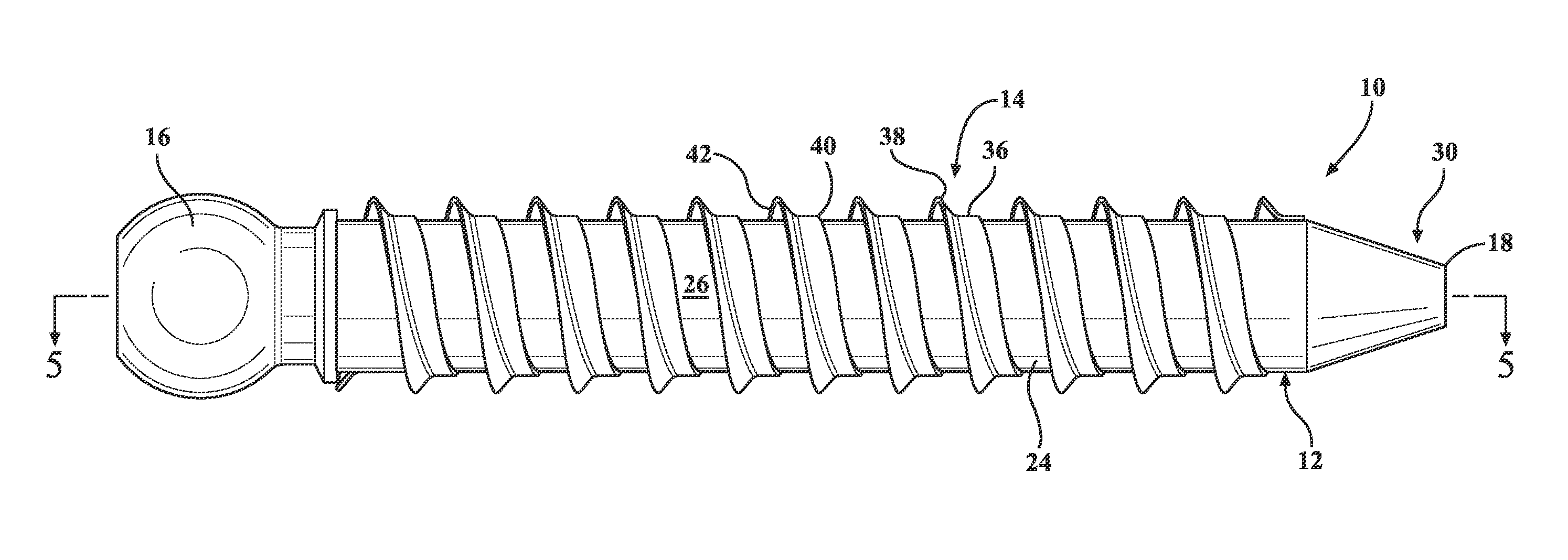
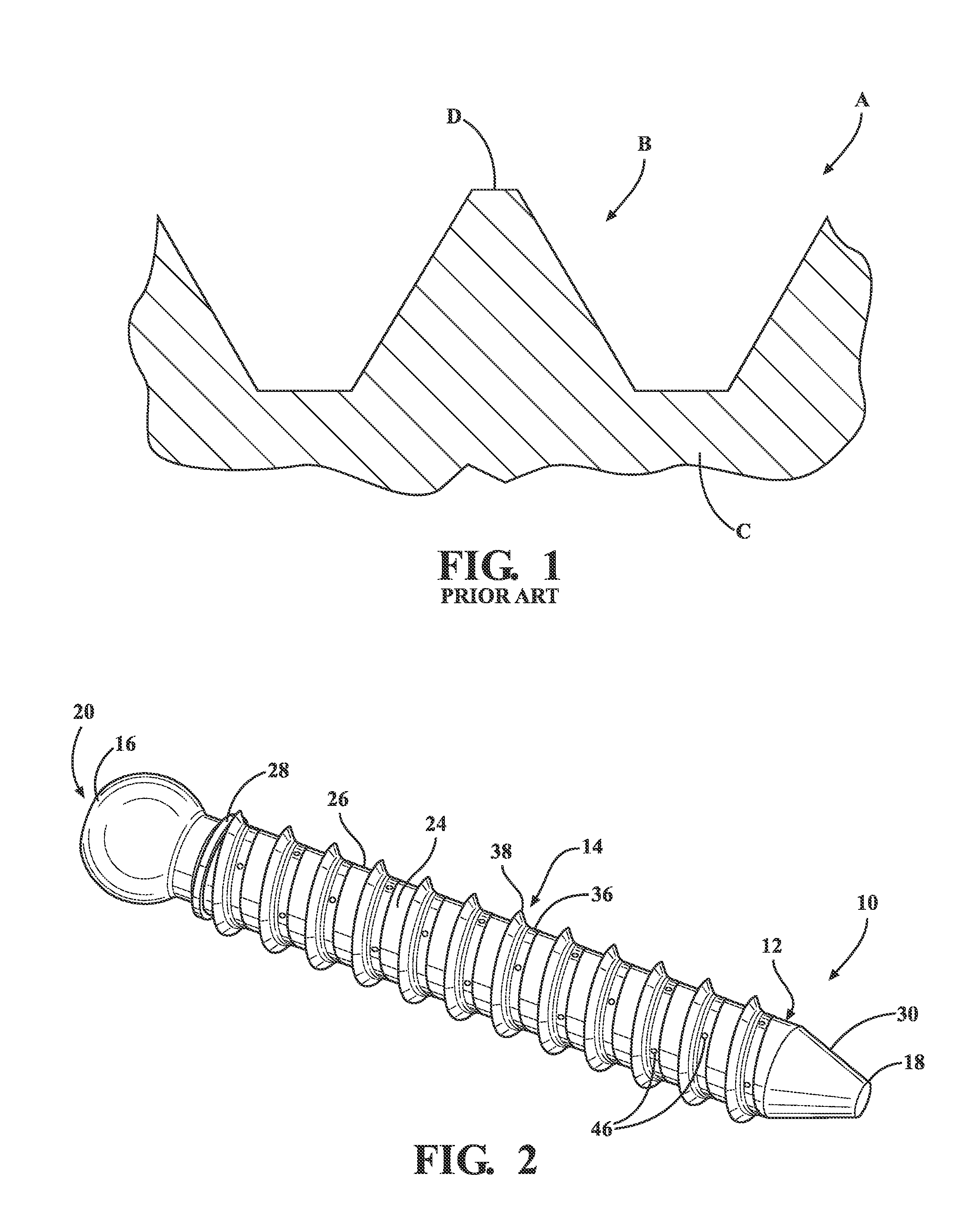
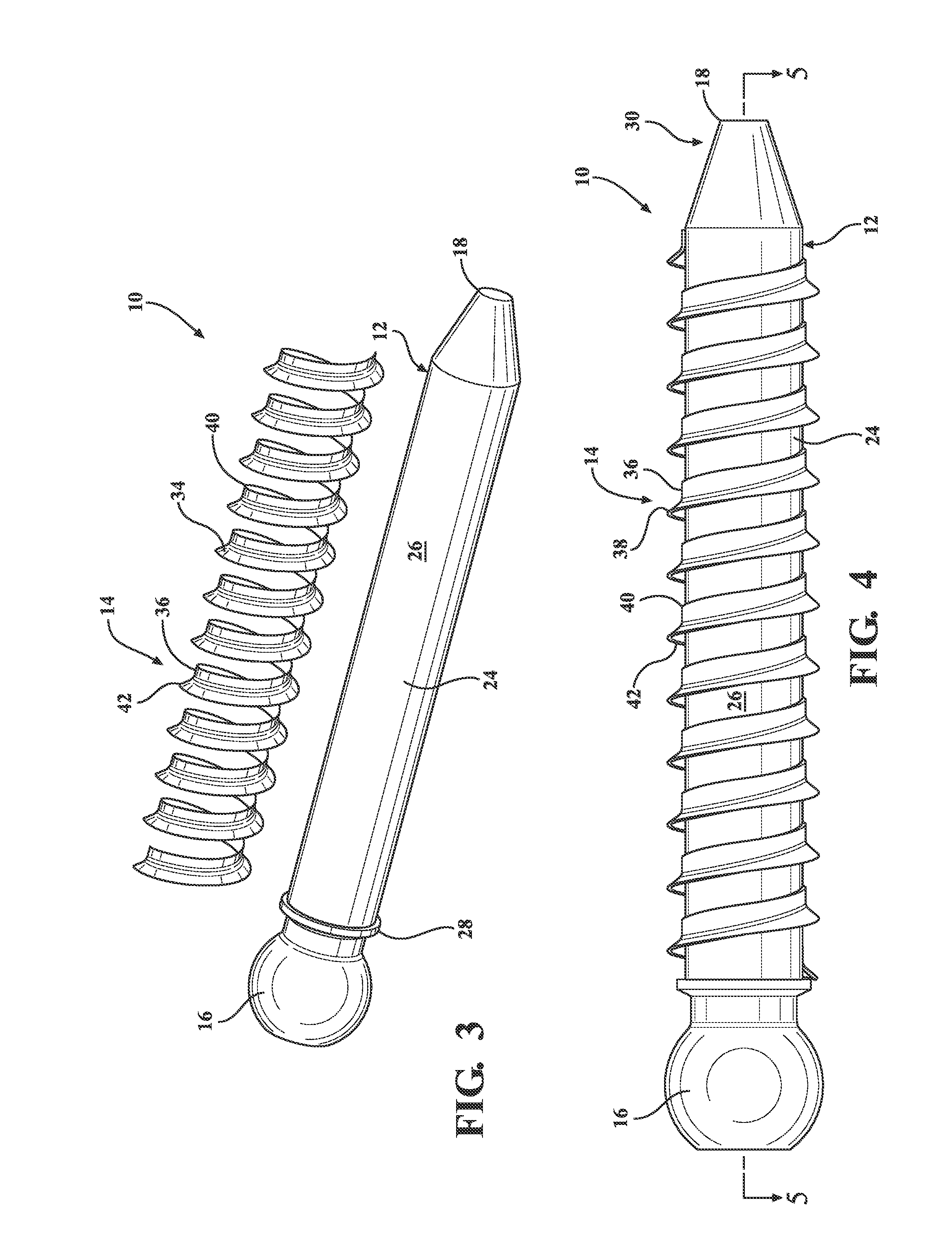
[0028]The embodiments described herein generally relate to an orthopedic screw having a shaft with a thread ribbon. The shaft includes a proximal driving end and a distal end. The thread ribbon includes a base portion and a flange portion. The base portion is rigidly secured to the shaft. The flange portion is may radially compress or expand relative to the base portion. The flange portion extends from the shaft at a first angle to provide the orthopedic screw with a first outer thread diameter in a first configuration. The flange portion extends from the shaft at a second angle to provide the orthopedic screw with a second outer thread diameter when subjected to a pull out force. The second outer thread diameter is greater than the first outer thread diameter. The increase in the outer thread diameter of the orthopedic screw increases the pull out strength required to remove the orthopedic screw from an insertion site without rotation.

[0029]With reference to FIGS. 2-4, an orthopedi...


PUM


Abstract

An orthopedic screw having a shaft and a thread ribbon is provided. The shaft includes a proximal driving end and a distal end. The thread ribbon extends around the shaft and including a base portion that is rigidly attached to the shaft and a flange portion that is resilient. The flange portion extends away from the shaft at a preset angle to form a preset outer thread diameter in a preset configuration. The flange portion extends away from the shaft at a second angle greater than the preset angle to form a second outer thread diameter greater than the preset outer thread diameter when the orthopedic screw is subjected to a pull out force.

Description

CROSS-REFERENCE TO RELATED APPLICATIONS[0001]This application claims priority of U.S. Provisional Application 62 / 059,657 filed Oct. 3, 2014, the contents of which are incorporated herein by reference.FIELD OF THE INVENTION[0002]An orthopedic screw for surgical procedures is provided. More particularly, the orthopedic screw is configured to have increased “pull out strength” while maintaining the ability for revisions to the screw site to facilitate subsequent procedures.BACKGROUND OF THE INVENTION[0003]Orthopedic screws are currently known and used for surgical procedures such as spinal fixation. Accordingly, it follows that fixation of an implant or fixation device is important. Fixation of the implant / fixation device is achieved by securing the implant or fixation device to the spine vis-à-vis the orthopedic screw.[0004]As shown in FIG. 1, previously known orthopedic screws A include an external thread B extending around a screw shaft C. The threads B of the previously known screw...

Claims


Application Information

Patent Timeline
IPC IPC(8): A61B17/86
CPCA61B2017/00867A61B17/8625A61B17/866A61B17/8685A61B17/869
Inventor REIMELS, WILLIAM
Owner ALPHATEC SPINE INC
Why Eureka
Try Eureka