

Contact strip structure
- Summary
- Abstract
- Description
- Claims
- Application Information
AI Technical Summary
Benefits of technology
Problems solved by technology
Method used
Image

Examples
first embodiment
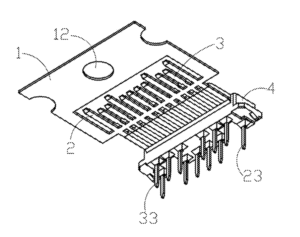
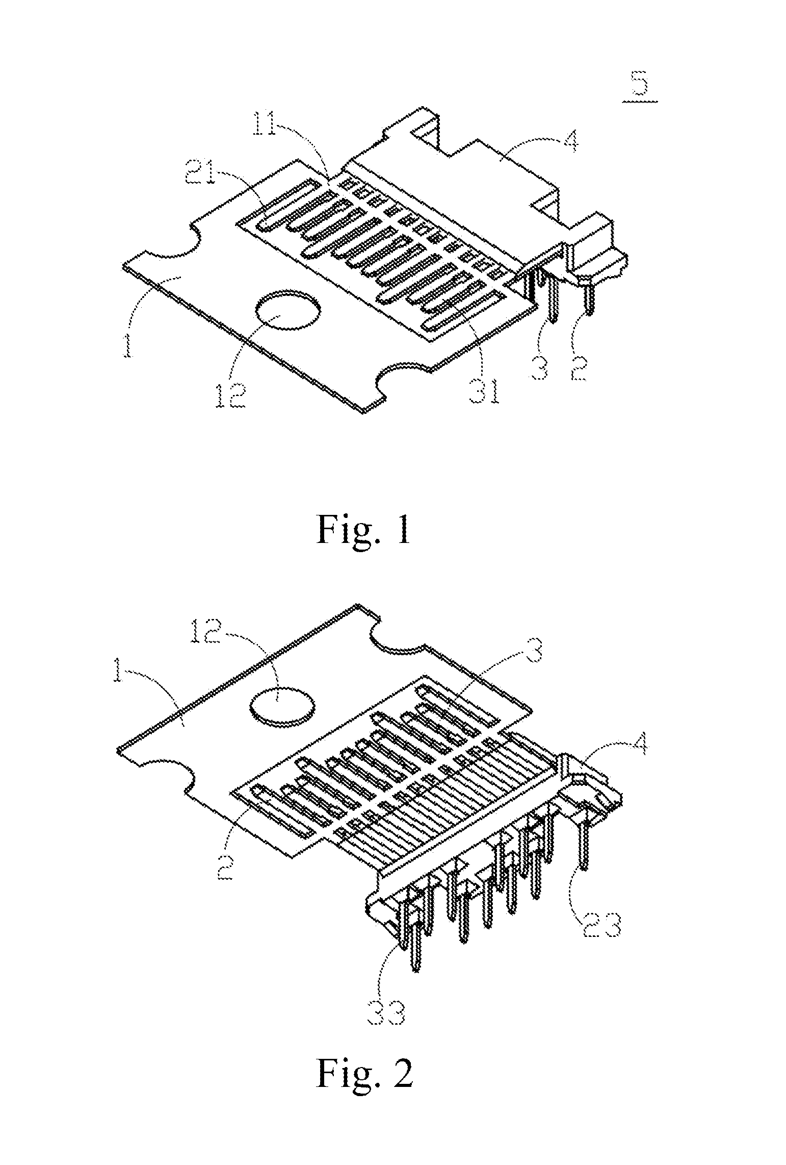
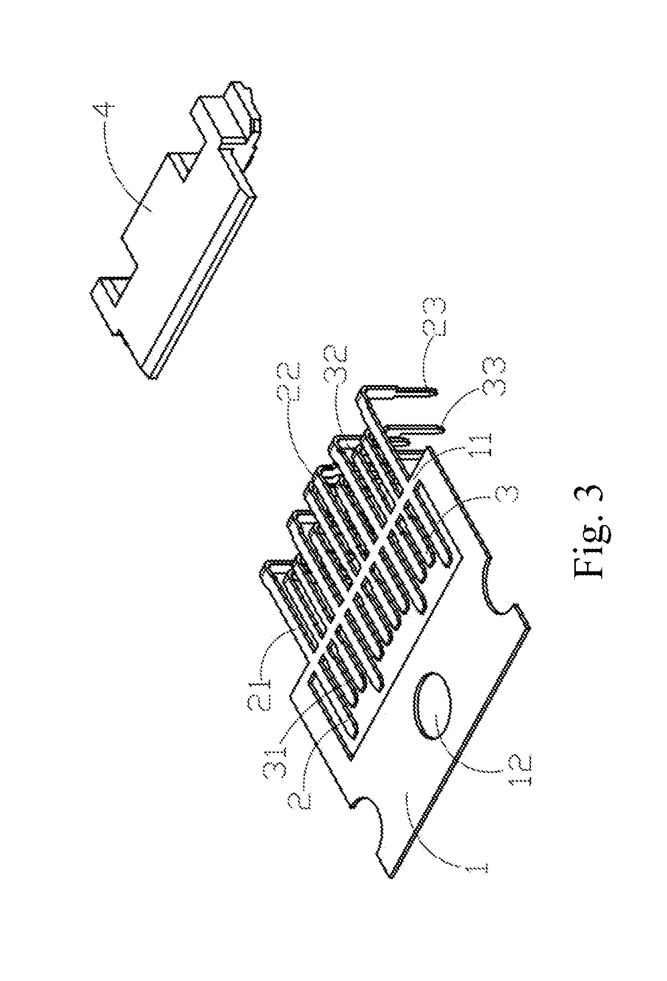
[0027]As shown in FIGS. 3-4, in the present disclosure, the strip 1 has a through hole 12 in the center. The through hole 12 is a positioning design configured to assist to fix the strip 1. When the strip 1 is driven during the operation of the transmission belt (not shown in FIGS. 3-4) in the manufacturing process, the through hole 12 can be detected by visual inspection using a detection pin (not shown in FIGS. 3-4) if the strip 1 is in position. The through hole is used to further fix the strip 1 for the subsequent formation by the bending of the first terminals 2 and the second terminals 3. Each of the first terminals 2 has a first contact portion 21, a first connecting portion 22, and a first holding portion 23, the first connecting portion 22 is formed by a vertical extension from the first contact portion 21, and the first holding portion 23 is formed by an extension from an end of the first connecting portion 22. Each of the second terminals 3 has a second contact portion 31...
second embodiment
[0030]As shown in FIGS. 5-8, in the present disclosure, as at a small spacing away from the first bridge 11, the strip 1 extends and mutually contacts with the first terminals 2 and the second terminals 3 to form a second bridge 13. The second bridge 13 and the first bridge 11 are arranged side by side, configured to increase the strength of the overall structure of each of the first terminals 2 and each of the second terminals 3.
PUM
 Abstract
Description
Claims
Application Information