Method and implant system for sacroiliac joint fixation and fusion

Active Publication Date: 2014-09-18
ORTHOCISION
View PDF15 Cites 65 Cited by
  • Summary
  • Abstract
  • Description
  • Claims
  • Application Information

AI Technical Summary

Benefits of technology

[0009]The present invention is an improved methods and devices for the immobilization or fusion of the Sacroiliac joi

Problems solved by technology

Lower back pain is a common ailment among the population and results in both pain and suffering as well as loss of work time.
While the sacroiliac joint has a limited range of motion, dysfunction of the joint has been identified.
In addition, complex spine surgeries, such as for correction of sagittal plane deformity, often require iliac fixation to maintain correction in patients with a high pelvic incidence or high risk of lumbo-sacral hardware failure.
High energy pelvic ring injuries that involve disruption of the SI joint and/or displaced fractures of the sacrum present unique challenges to the orthopedic traumatologist.
Some sacral fractures require solid posterior stabilization, which may be difficult to achieve with typical treatment methods.
Furthermore, vertically unstable sacral fractures/SI joint disruptions have a relatively high incidence of neurovascular injury and may require unique stabilizat

Method used


Image

  • Method and implant system for sacroiliac joint fixation and fusion
  • Method and implant system for sacroiliac joint fixation and fusion
  • Method and implant system for sacroiliac joint fixation and fusion

Examples


Example

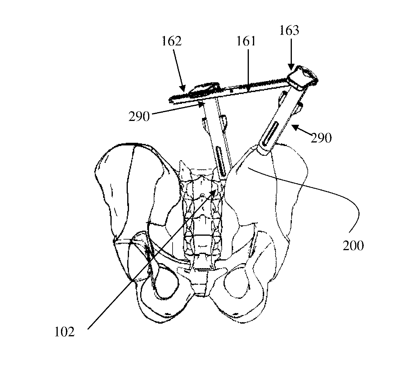
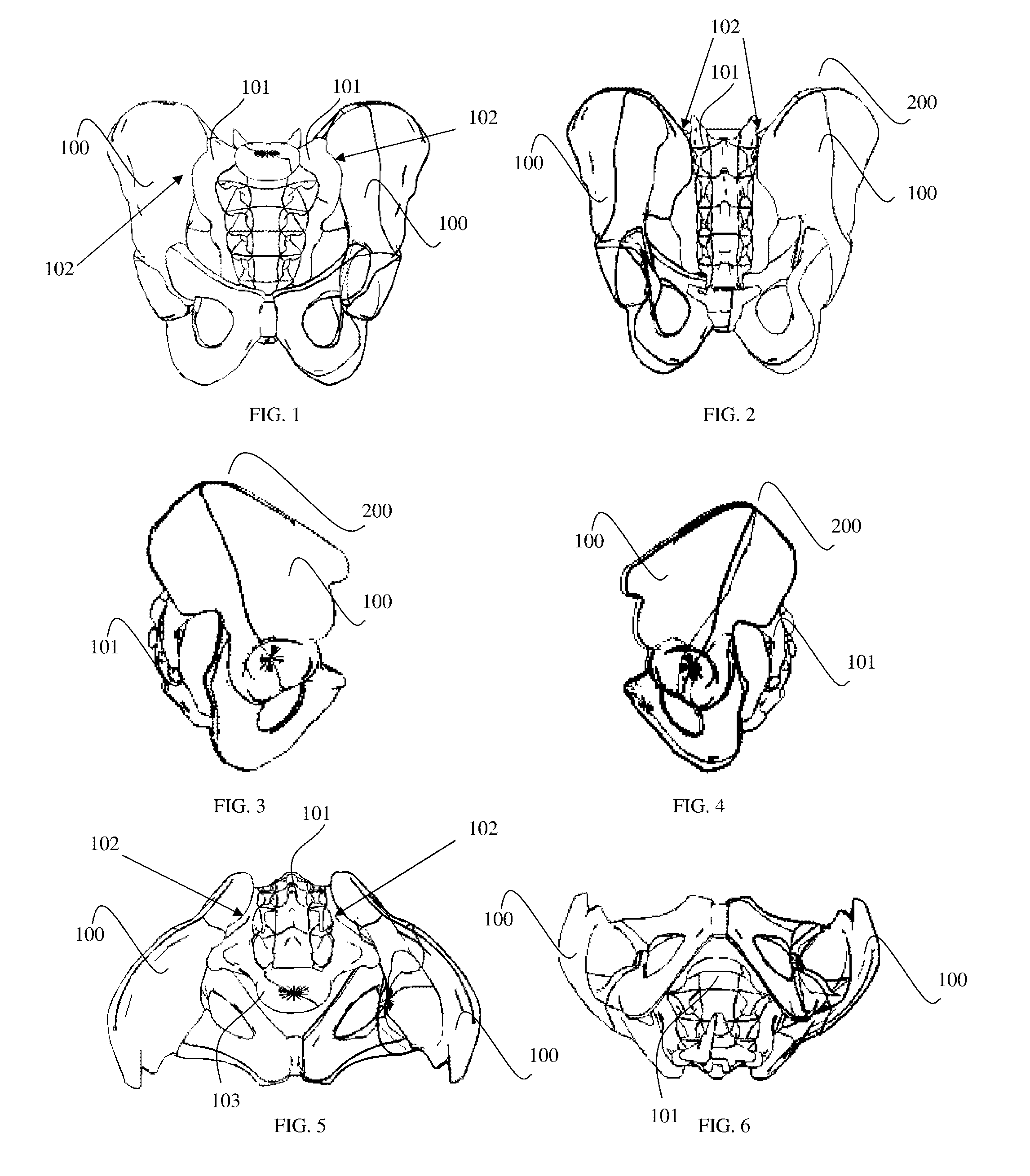
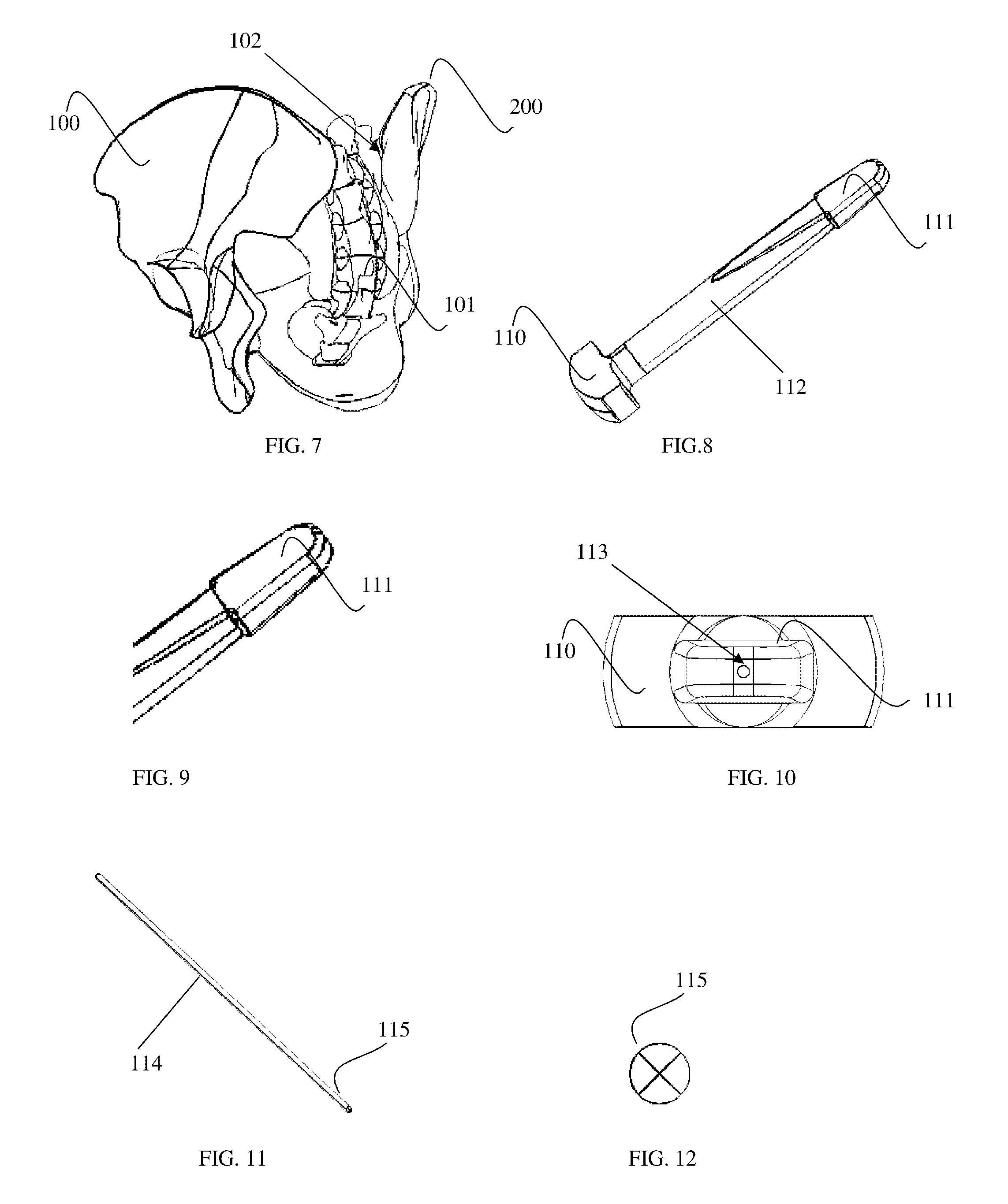
[0102]Reference will now be made in detail to certain embodiments of the invention, examples of which are illustrated in the accompanying drawings. While the invention will be described in reference to these figures and certain implementations and examples of the embodiments, it will be understood that such implementations and examples are not intended to limit the invention. To the contrary, the invention is intended to cover alternatives, modifications, and equivalents that are included within the spirit and scope of the invention as defined by the claims. In the following disclosure, specific details are given to provide a thorough understanding of the invention. References to various features of the “present invention” throughout this document do not mean that all claimed embodiments or methods must include the referenced features. It will be apparent to one skilled in the art that the present invention may be practiced without these specific details or features.

[0103]Reference ...


PUM


Abstract

An improved method of implanting a bone graft in a joint and tools for accomplishing the same is disclosed. The present invention relates generally to tools and methods useful for treating a sacroiliac joint. In one embodiment, the present invention is a method including the steps of: creating a first incision in the patient's skin proximal to the patient's sacroiliac joint; creating an incision in the patient's skin over the patient's ilium; inserting a first working channel into said first incision and spreading said sacroiliac joint with an inserted end of said first working channel; inserting a second working channel into said second incision and forming a hole in said ilium; creating a void in said sacroiliac joint; inserting a graft into said void; and inserting a joint fusing device into said ilium and said sacrum.

Description

FIELD OF THE INVENTION[0001]The present invention relates generally to medical devices and medical methods. More particularly, the present invention relates to musculoskeletal surgical methods and associated surgical tools for treatment of the sacroiliac joint.DISCUSSION OF THE BACKGROUND[0002]Lower back pain is a common ailment among the population and results in both pain and suffering as well as loss of work time. Thus, approaches for the treatment of back pain can both relieve suffering as well as reduce employee down time. Thus, effective treatments for lower back pain have both economic benefits as well as the benefit of alleviating considerable suffering.[0003]The sacroiliac joint is located at the juncture of the ilium, the upper bone of the pelvis, and the sacrum at the base of the spine. While the sacroiliac joint has a limited range of motion, dysfunction of the joint has been identified. The joint is supported by a range of ligaments including, for example, the sacroilia...

Claims


Application Information

Patent Timeline
IPC IPC(8): A61F2/46A61B17/17
CPCA61B17/1757A61F2/4611A61B17/1671A61B17/7055A61F2/4455A61F2002/30995A61F2/447A61F2002/30785A61F2002/30828A61F2002/30904A61B17/8605A61B17/869A61B17/8872
Inventor SCHIFANO, TROYANDERSON, STEVETHAIYANANTHAN, GOWRIHARAN
Owner ORTHOCISION
Why Eureka
Try Eureka