Patient alignment device

Active Publication Date: 2009-06-04
YANG JUN
View PDF3 Cites 31 Cited by
  • Summary
  • Abstract
  • Description
  • Claims
  • Application Information

AI Technical Summary

Benefits of technology

[0013]The invention has the further object of facilitating medical procedures by eliminating the need for personnel to make manual adjustments of the position of a patient's body.
[0014]The invention has the further object of reducing the physical demands imposed on an operator of a medical procedure when it is necessary to adjust th

Problems solved by technology

It is difficult for the patient to know his own orientation, and t

Method used


Image

  • Patient alignment device
  • Patient alignment device
  • Patient alignment device

Examples


Example

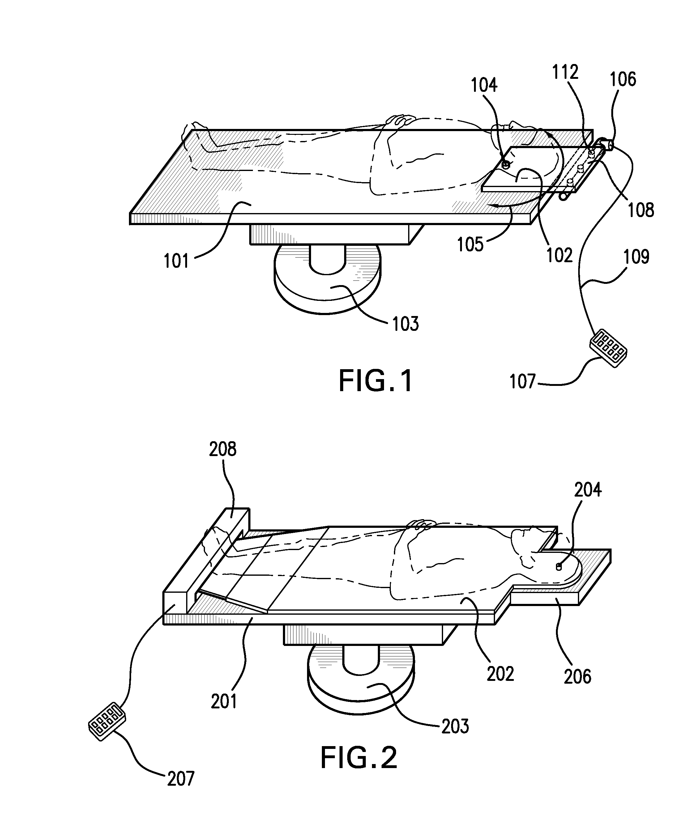
[0028]FIG. 1 provides a perspective view, showing a first embodiment of the patient alignment device of the present invention. The device includes table 101 which is supported by stand 103. A head-support plate 102 is connected to the table by pin 104. The plate 102 can pivot or rotate about the pin.

[0029]A motor 106 drives a rotatable threaded shaft 108. Connecting members 112 threadedly engage the threaded shaft, and convert the axial motion of the threaded shaft into translational motion of the connecting members, which in turn move the plate 102. That is, rotation of the threaded shaft causes the plate to pivot in either direction indicated by arrow 105. More details of the structure of the motor, the threaded shaft, and the connecting members are given later, in the discussion of a further embodiment.

[0030]The motor is chosen to be capable of bidirectional motion, so that it can rotate the shaft in either direction. In one preferred embodiment, the motor is a step motor.

[0031]R...


PUM


Abstract

A patient alignment device includes a table and a rotatable member positioned to rotate relative to the table. The rotatable member may be a head-support plate or a board which supports substantially all of a patient's body. A motor moves the board or plate so as to align the patient's body, or a part of the body, in a desired direction. The board may be formed in two segments, the segments being selectively connectable to each other, the segments also being selectively connectable to the table by pins, at various possible pivot points. Positioning of the pins determines the mode of rotation of the board. The invention allows an operator to align the patient's body with precision, by remote control, and without interrupting the medical procedure.

Description

CROSS-REFERENCE TO PRIOR APPLICATION[0001]Priority is claimed from U.S. Provisional Patent Application Ser. No. 61 / 004,730, filed Nov. 30, 2007, the disclosure of which is incorporated by reference herein.BACKGROUND OF THE INVENTION[0002]The present invention relates to the field of medical procedures, including surgery or other therapy, and diagnostic procedures, and provides a method and apparatus for positioning a patient in a desired orientation.[0003]Radiation therapy, diagnostic imaging, surgery, and other medical procedures often require that a patient's head or body be aligned parallel to the center axis of a table, or other support, or to some other preferred orientation. It may be necessary to align the patient's head or body immediately before, or during, the medical procedure.[0004]It is difficult for the patient to know his own orientation, and the patient may change his or her orientation during the procedure. Therefore, the personnel conducting the procedure need to a...

Claims


Application Information

Patent Timeline
IPC IPC(8): A47B7/00
CPCA61B6/0457A61G13/02A61G13/1295A61G13/121A61G13/10A61B6/0487
Inventor YANG, JUNFENG, JING
Owner YANG JUN
Why Eureka
Try Eureka