Thermal printer and program

Active Publication Date: 2016-04-07
SATO HLDG CORP
View PDF1 Cites 7 Cited by
  • Summary
  • Abstract
  • Description
  • Claims
  • Application Information

AI Technical Summary

Benefits of technology

[0018]By using the thermal printer and the program therefor according to the present invention, deformation of an unprinted label

Problems solved by technology

Therefore, if the label is left for a long period of time in a state where it is sandwiched between the thermal head and the platen roller, the label may deform, e.

Method used


Image

  • Thermal printer and program
  • Thermal printer and program
  • Thermal printer and program

Examples


Example

First Embodiment

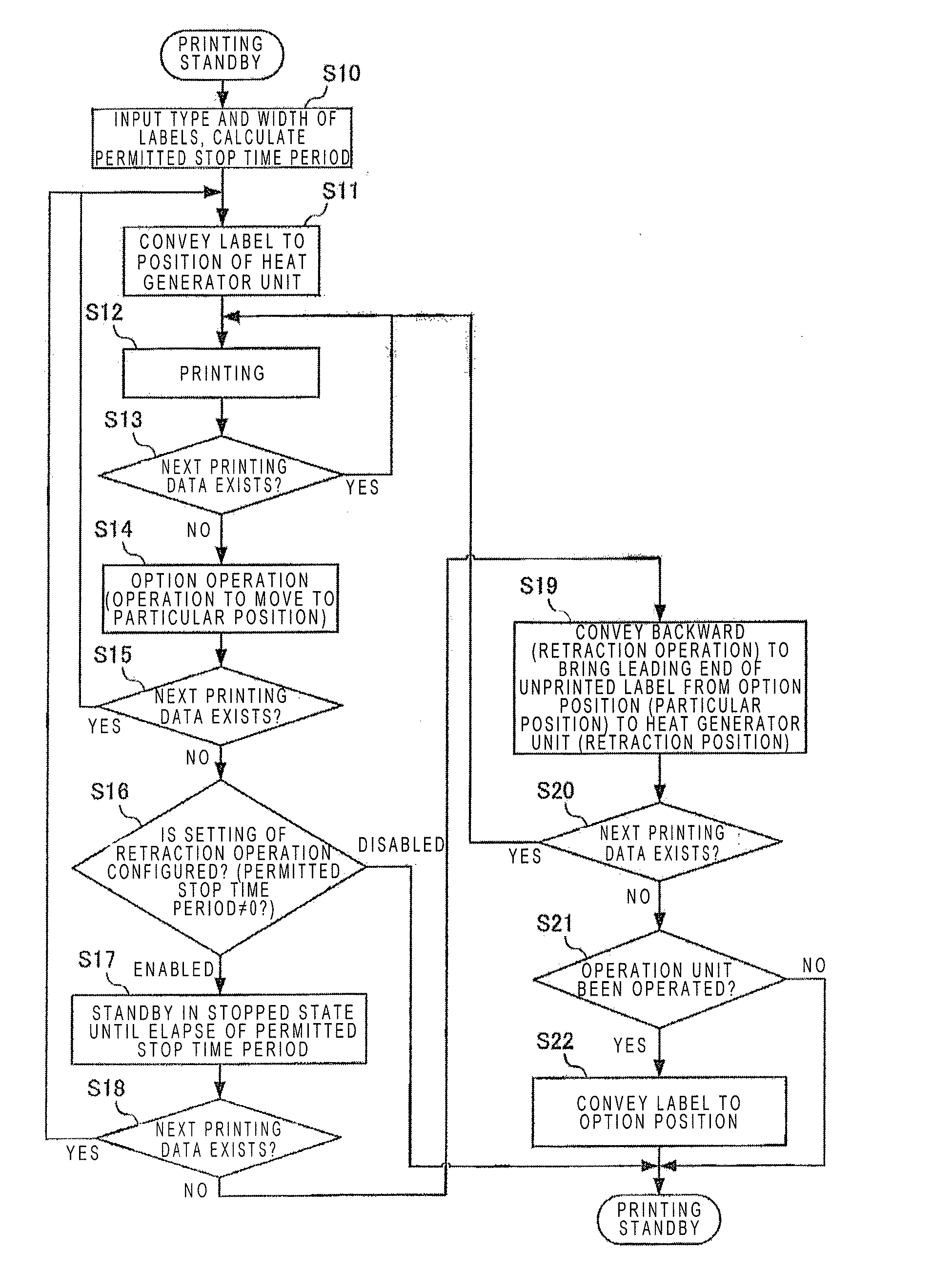
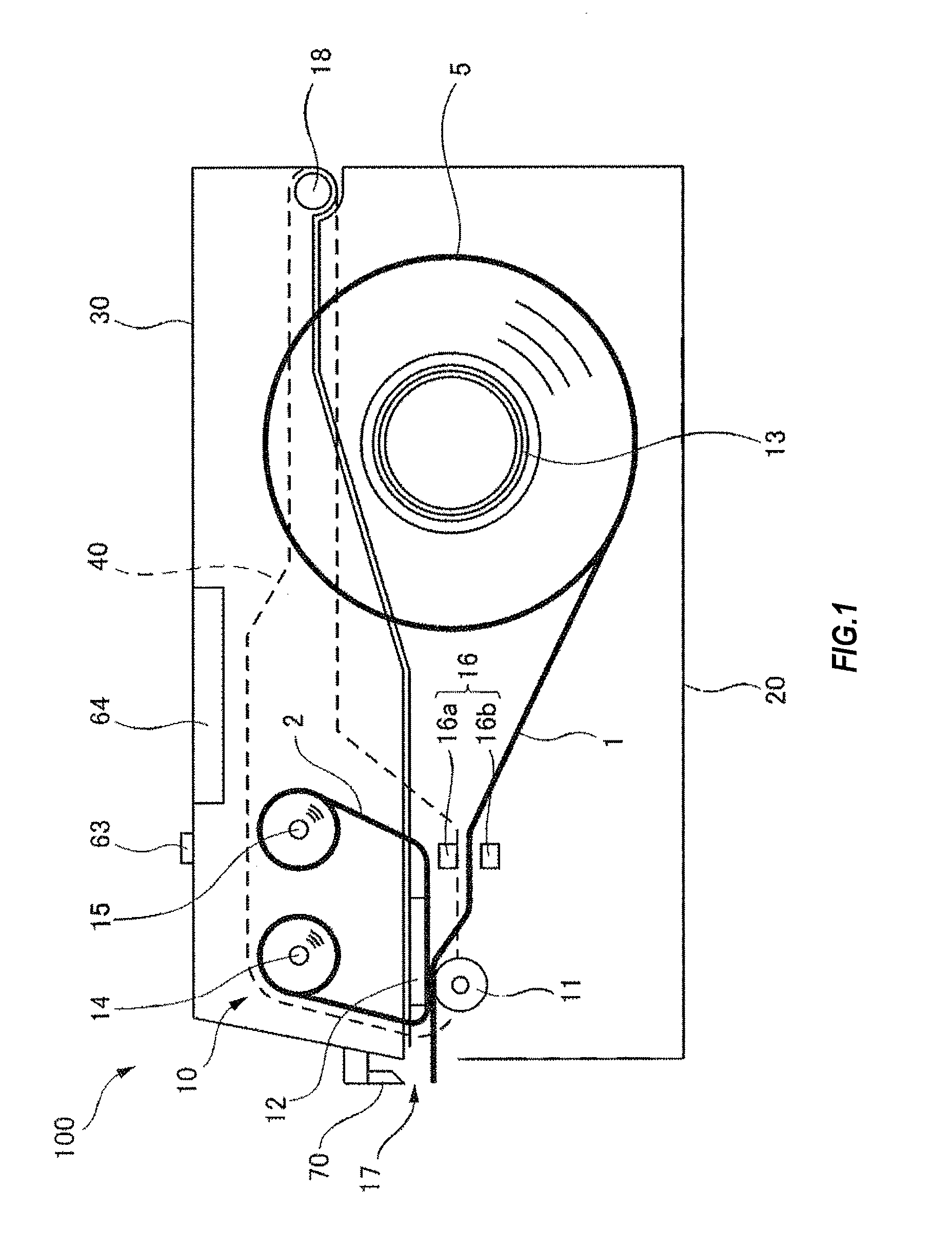
[0024]FIG. 1 is a schematic side view showing a configuration of a thermal printer 100 according to a first embodiment of the present invention. It should be noted that each of the figures discussed below, including FIG. 1, is a schematic illustration in which the size and shape of each component are exaggerated as appropriate to facilitate the understanding. Furthermore, although specific numerical values, shapes, materials, and the like are presented in the following description, they can be changed as appropriate. In addition, in the present specification and the claims, output of various types of information by a thermal printer is expressed as “printing”, which is a common practice among those skilled in the art. It should be noted that, as just stated, the expression “printing” refers to output of information by a thermal printer. It will be assumed that the expression “printing” is not limited to the output of characters, and has a broad meaning including the ...

Example

Second Embodiment

[0062]The thermal printer 100 according to a second embodiment is similar to the thermal printer 100 according to the first embodiment, except that the configuration of the thermal head 12 and the operations of the control unit 150 partially differ between the first embodiment and the second embodiment. Therefore, the components that fulfil functions similar to the functions of the above-described first embodiment are given the same reference numerals, and a redundant description is omitted as appropriate.

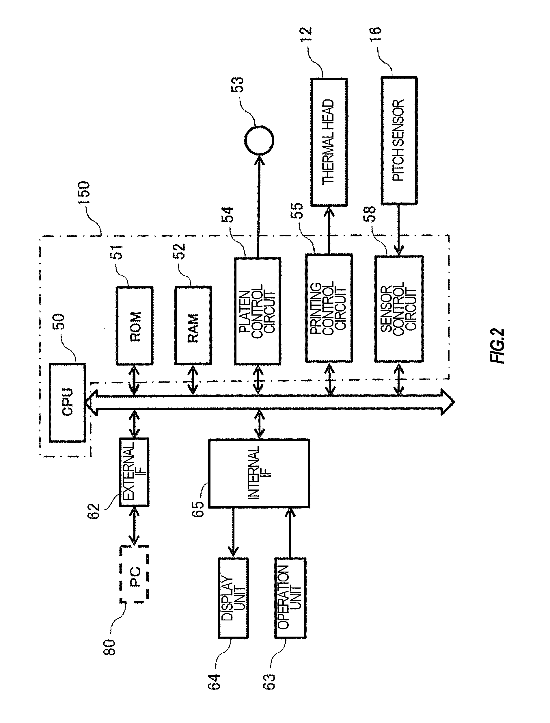
[0063]The thermal head 12 according to the second embodiment is configured such that it can adjust pressure applied to the platen roller 11. The thermal head 12 may adjust applied pressure using any method, including various types of methods that are conventionally known. In addition, in the thermal printer 100 according to the present embodiment, the control unit 150 can be informed of a value at which the current applied pressure is adjusted using, for example, a...


PUM


Abstract

A thermal printer includes a control unit that performs control to perform: an option operation, whereby upon completion of printing on a label provided on a continuous label body, the printed label is conveyed to a particular position and then conveyance of the continuous label body is stopped; and a retraction operation, whereby when a preset permitted stop time period has elapsed since the stop of conveyance of the continuous label body without performing next printing during the permitted stop time period, an unprinted label retracts to a retraction position where at least a printing region of the unprinted label is not sandwiched between a platen roller and a thermal head. The control unit can change the permitted stop time period for each type and/or each width of a label to be printed.

Description

TECHNICAL FIELD[0001]The present invention relates to a thermal printer that performs printing with heat generated by a thermal head, and a program.BACKGROUND ART[0002]Some thermal printers can perform an option operation, such as a tear-off operation and a peeling operation. In the option operation, printed labels are sometimes conveyed to a predetermined position (referred to as an option position) and then stopped after printing has been performed on the designated number of labels. For example, in the tear-off operation, a liner is automatically advanced until a portion of the liner between a printed label and the next unprinted label arrives at the position of a cutter, and then the liner is stopped. In the peeling operation, a liner is automatically advanced until a printed label arrives at a position where it is peeled off, and then the liner is stopped.[0003]A thermal printer performs printing while conveying a label in a state where the label is sandwiched between a thermal...

Claims


Application Information

Patent Timeline
IPC IPC(8): B41J13/00B41J2/32B41J11/04
CPCB41J13/0009B41J2/32B41J11/04B41J2/325B41J11/42B41J3/4075
Inventor KOJIMA, MICHITAKA
Owner SATO HLDG CORP
Why Eureka
Try Eureka