Fish Tape Adaptor for Powered Retraction of the Fish Tape

a technology of adaptor and fish tape, which is applied in the direction of rigid shaft couplings, couplings, couplings, etc., can solve the problems of wasting valuable time and energy of the electrician, difficulty in pulling long amounts of wire or string through the conduit, and inefficient procedures

Inactive Publication Date: 2016-04-07
RYALS JONATHAN
View PDF0 Cites 6 Cited by
  • Summary
  • Abstract
  • Description
  • Claims
  • Application Information

AI Technical Summary

Problems solved by technology

One problem with current fish tape devices is that it is very difficult to pull lengthy amounts of wire or string through the conduit.
Such a procedure is often inefficient, fatiguing, and potentially dangerous.
To compound the problem, conventional manually-operated fish tape devices require that the fish tape then be wound about the reel, which wastes valuable time and energy of the electrician.
Powered fish tape devices, however, typically include a high number of parts and a sophisticated series of gears, both of which involve high complexity and cost.
Furthermore, these devices typically employ their own integrated motors, thus having no adaptability or interoperability with existing fish tape devices.
However, it has been shown that a central drive for such a reeling device is prone to breaking due to the large stresses that may come to bear when reeling in a long length of metal tape.
This feature also negates the normal operation of the hand-held tool.
However, manually rotating the reel 12 relative to the handle 16 when reeling in the tape can be tiresome, laborious, and inefficient.
First, the attachment embodiment appears difficult to secure and, as described above, is likely to wobble under higher speeds and continued use.

Method used


Image

  • Fish Tape Adaptor for Powered Retraction of the Fish Tape
  • Fish Tape Adaptor for Powered Retraction of the Fish Tape
  • Fish Tape Adaptor for Powered Retraction of the Fish Tape

Examples


Embodiment Construction

Side Reel Adaptor

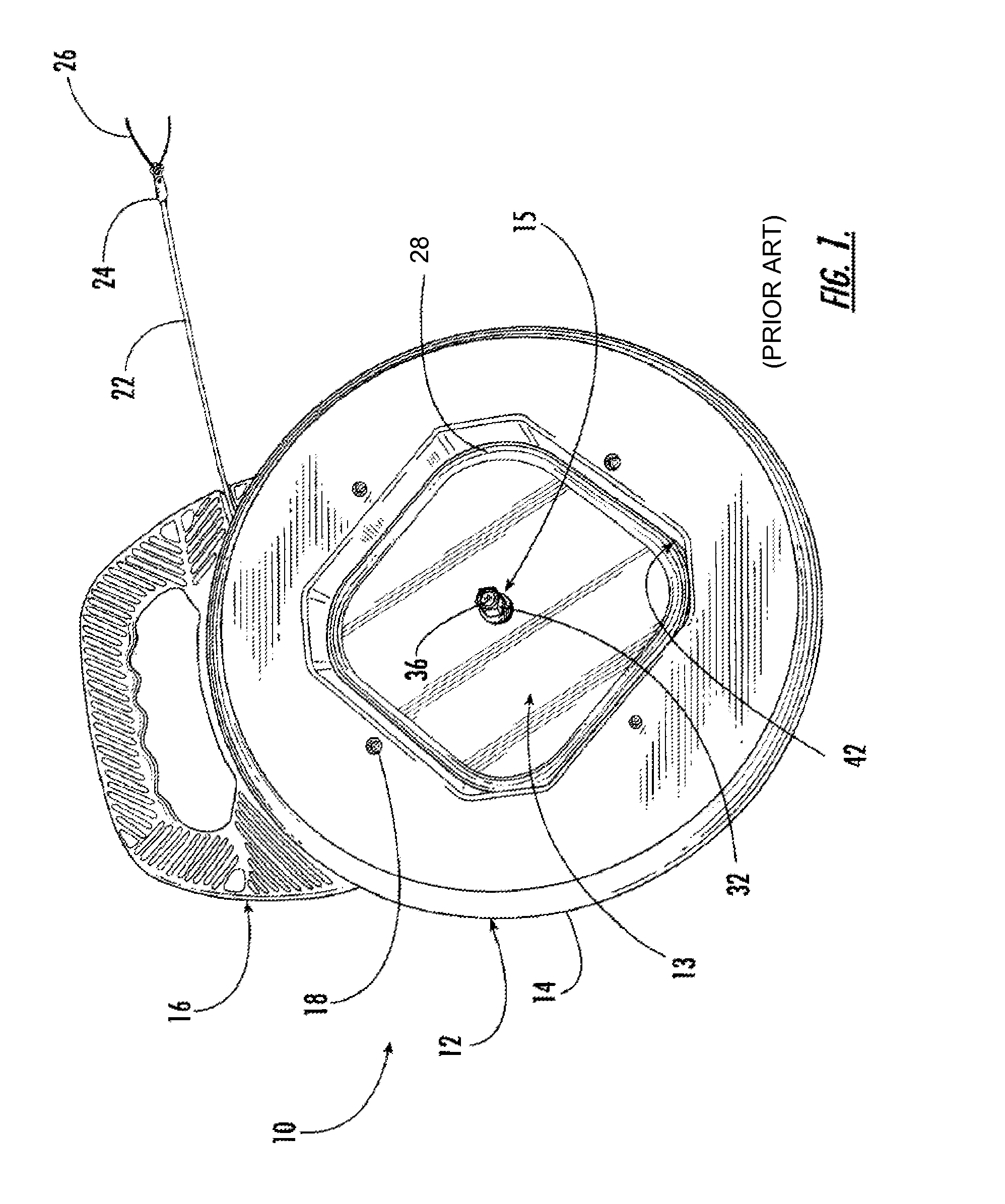
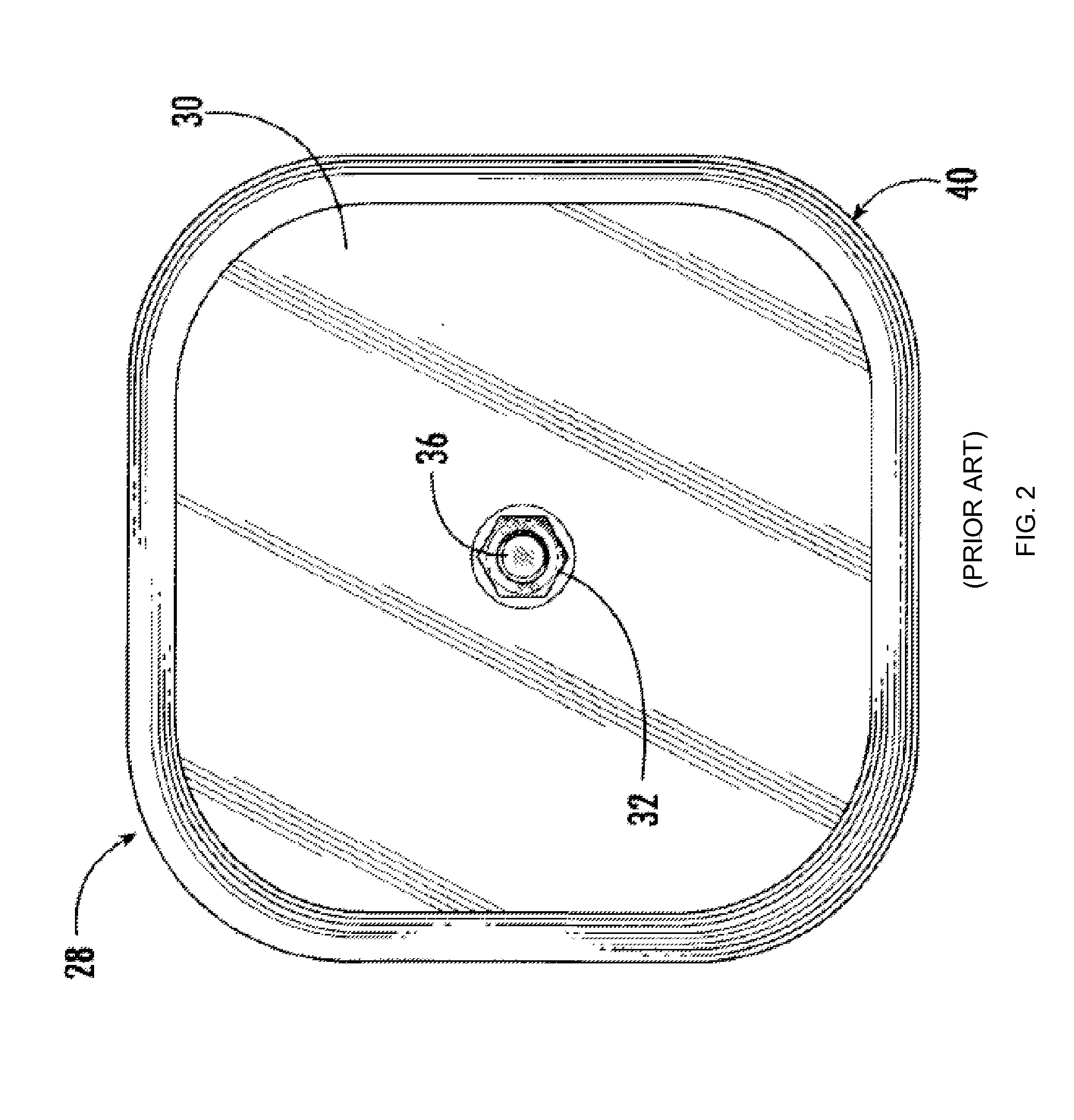
[0027]As described above, the device described by Yates has at least four problems. First, the attachment embodiment appears difficult to secure and, as described above, is likely to wobble under higher speeds and continued use. Second, the center drive device 28 of FIG. 1 completely fills central opening 13, preluding its use in manual retraction. Third, a different center drive device 28 has to be used for each different type and size of fish tape reel, since the central opening 13 varies among types and sizes of fish tape reels. Four, integrally forming center drive device 28 requires modification of existing reels.

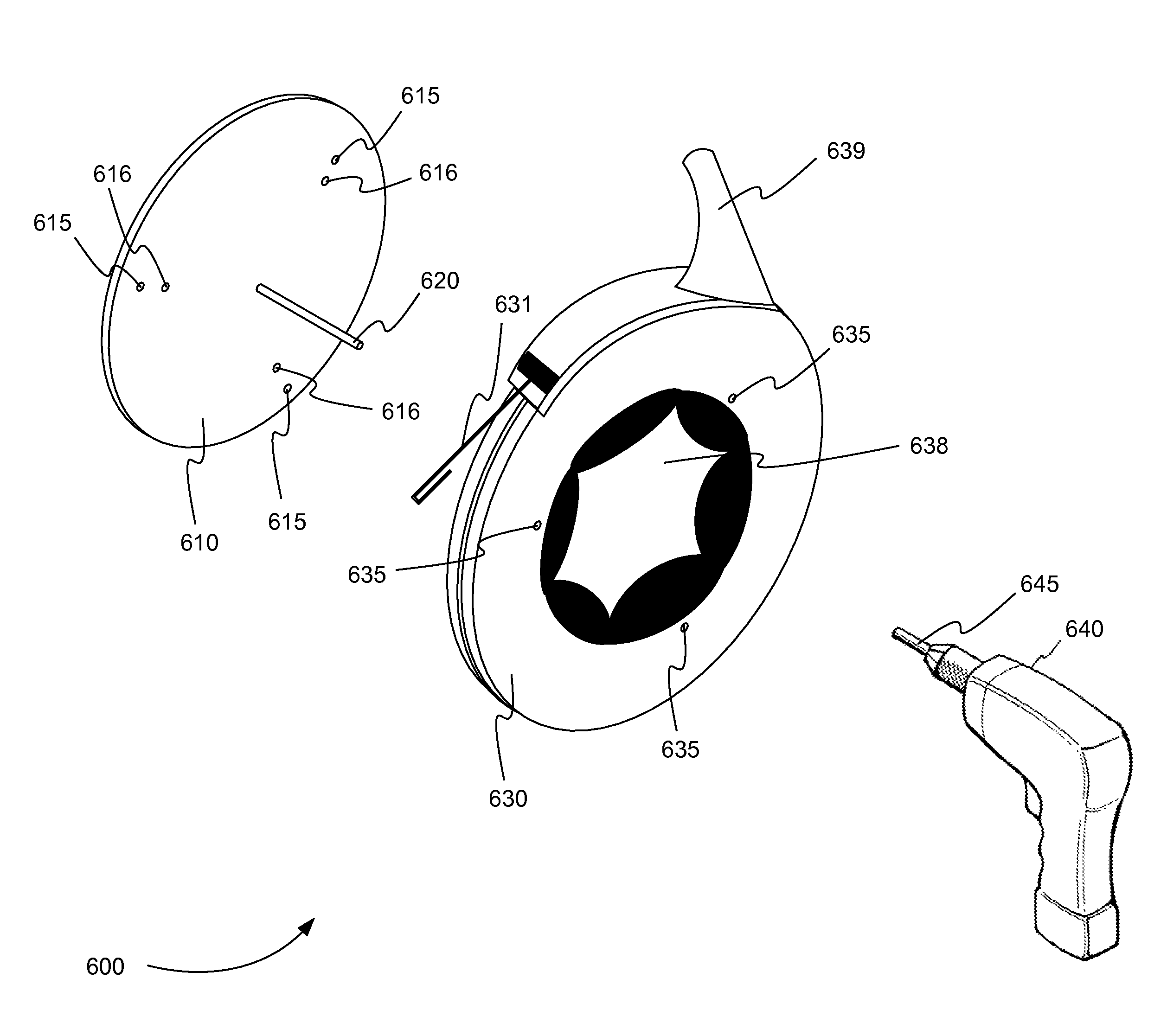
[0028]In various embodiments, a side reel adaptor provides a secure attachment for existing fish tape reels, allows the central opening of existing fish tape reels to be used manual retraction, and requires no modification to existing fish tape reels.

[0029]FIG. 3 is a top view 300 of an exemplary side reel adaptor 310, in accordance with various embodi...


PUM


Abstract

A side reel adaptor for a fish tape reel allows the fish tape reel to be spun with a drill. In one embodiment, the side reel adapter includes an attachment plate and a central bit. The attachment plate includes a plurality of holes that are aligned with the screw holes of one or more fish tape reels so that the attachment plate can be attached to the side of the one or more fish tape reels using the screws of the one or more fish tape reels. The central bit is connected to the center of the attachment plate so that the central bit is perpendicular to the attachment plate. The central bit is adapted to accept a drill chuck so that a drill can spin attachment plate about the axis of the central bit and, in turn, spin the fish tape reel attached to the attachment plate.

Description

CROSS-REFERENCE TO RELATED APPLICATION[0001]This application claims the benefit of U.S. Provisional Patent Application No. 62 / 058,627 filed Oct. 1, 2014.INTRODUCTION[0002]Fish tape is used in many trades to pull wire through a conduit. In order to do this, one first pushes a narrow metal strip, or tape, through the conduit. The wire is then attached to the extended end of the metal tape and the metal tape is then retracted through the conduit, pulling the wire through the conduit as well.[0003]Modern fish tapes devices often incorporate a reel such that the fish tape is wound around the reel by manually rotating the reel about a handle. More specifically, the reel is formed as a flattened ring-shaped rotatable body having a slot formed all the way around its outer circumference. The reel is usually formed in two generally mirror-image halves that fit together so as to create an interior space for storing the fish tape. The reel has an inner hub on which the fish tape is wound. The f...

Claims


Application Information

Patent Timeline
Patent Type & Authority Applications(United States)
IPC IPC(8): B65H75/44B65H75/40F16D1/00
CPCB65H75/4481F16D1/00B65H75/406F16D2300/12B65H2701/376B65H75/305B65H2701/355F16D1/101F16D2001/102
Inventor RYALS, JONATHAN
Owner RYALS JONATHAN
Why Eureka
Try Eureka