
Arresting element and handle

a technology of a handle and a handle, which is applied in the field of a handle and a sling, can solve the problems of not being able to operate during normal operation, the door handle cannot be already opened, and the unintended opening cannot be avoided

Inactive Publication Date: 2016-04-07
HUF HULSBECK & FURST GMBH & CO KG
View PDF1 Cites 6 Cited by
  • Summary
  • Abstract
  • Description
  • Claims
  • Application Information

AI Technical Summary

Benefits of technology

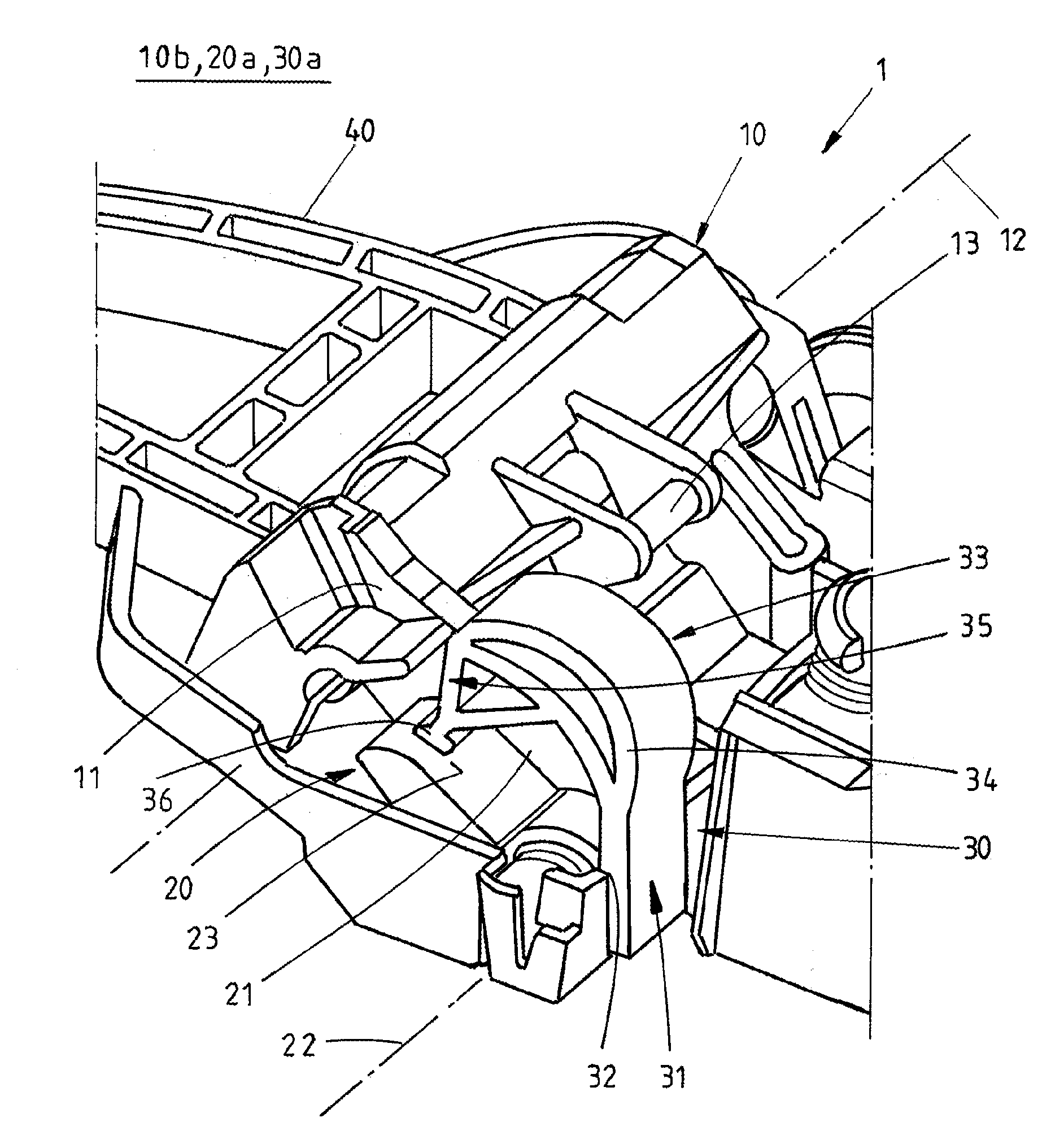
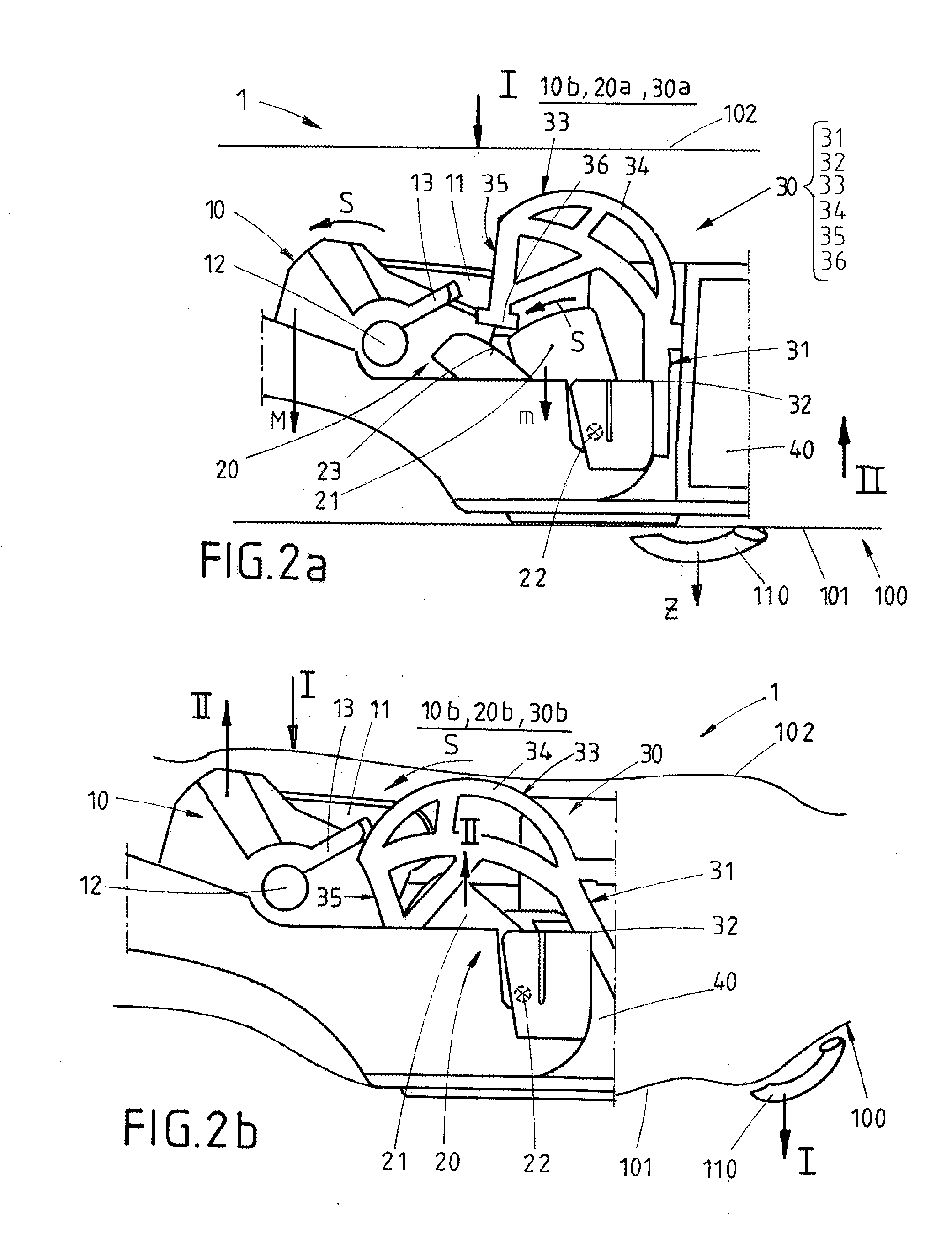
The invention is a locking device for a vehicle door that includes an arresting element for arresting the blocking element of the locking device in case of a deformation of the door panel, particularly the inner door panel. The arresting element can be refitted to an existing locking device without altering its geometry. The sensor area can detect the deformation of the inner door panel and the arresting element can arrest the blocking element in its blocking position to secure the vehicle. The handle can also provide an arresting element that can be moved between a released position and an arresting position to prevent the blocking element from being jammed or disturbed in its function. The arresting element is designed to arrest the blocking element in its blocking position, ensuring reliable functioning of the locking device in case of an accident.

Problems solved by technology

However, it is not operated during normal operation and is in its resting position.
During an accident impact forces and accelerations can have an effect on the vehicle door, which can lead to the fact that the door handle is skidded into the unlocking direction, which opens the door lock.
If however during the accident the door panel, particularly the outer door panel, is damaged, the mass balancing element can however be pushed into its released position, in which the unintended opening of the door cannot be avoided.
Thereby, the disadvantage has occurred that by this deformation the door handle can be already transferred in its unlocking position opening the door lock despite of the mass balancing element and the blocking element.
At the same time it can occur that the blocking element is clamped and cannot be released functionally anymore and cannot lock the mass balancing element anymore.
As a consequence the vehicle door can be opened, wherein an increased risk of injury for the person sitting within the vehicle occurs.

Method used


Image

  • Arresting element and handle
  • Arresting element and handle
  • Arresting element and handle

Examples


Embodiment Construction

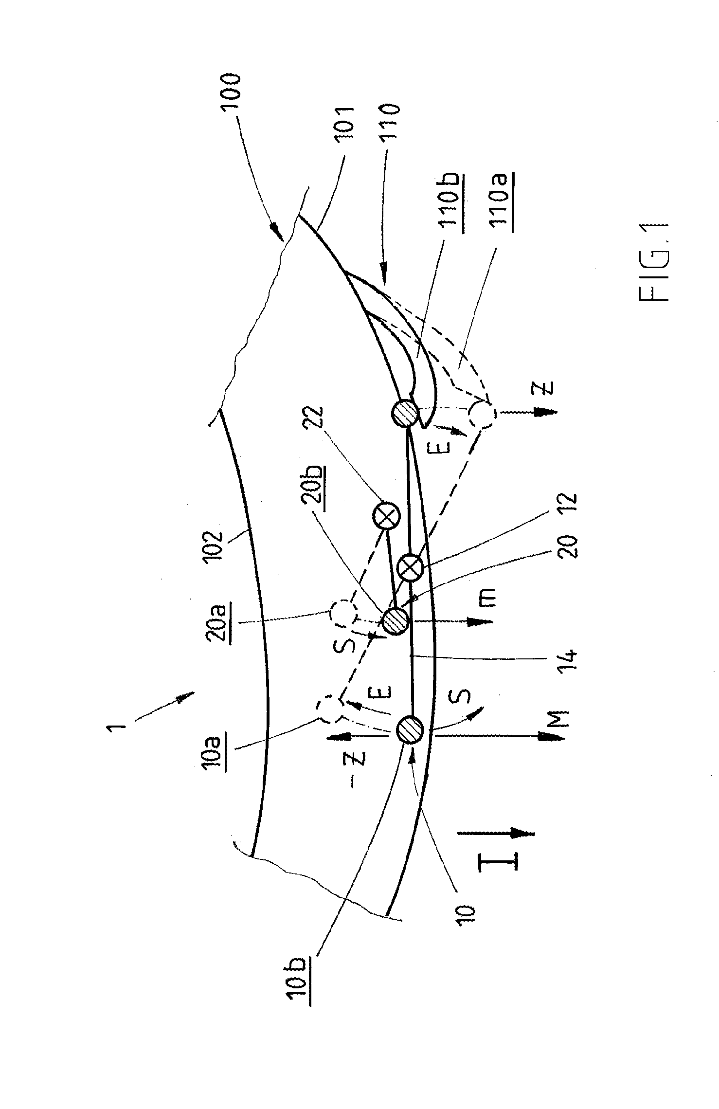
[0029]FIG. 1 shows a common handle 1 according to the state of the art which is likewise called crash-lock. The handle 1 is assembled in locking devices at vehicle doors 100 between an outer 101 and an inner door panel 102 and shall avoid that the door handle 110 is swivelled from a locking position 110a into an unlocking position 110b in case of an accident and that the vehicle door is opened undesirably. Therefor the common handle 1 is configured with a mass balancing element 10, which is used for securing the door handle 110 due to its inertia force M. The handle 1 comprises a transmission element 14, which is kind of a rocker between the door handle 110 and the mass balancing element 10. The mass balancing element 10 is thereby pivotably mounted about an axis 12 in a way that the transmission element 14 configures the lever of the rocker. This transmission element 14 can transmit the tensile force Z at the door handle 110 in an unlocking position 110a opening the door lock to th...


PUM


Abstract

The invention relates to an arresting element (30) for a blocking element (20) of a locking device of a vehicle door (100), with a fixing area (31) for fixing the arresting element (30) at the locking device, a sensor area (33) for detecting a deformation of a door panel (101, 102) of the vehicle, particularly an inner door panel (102), which is directed towards the interior of the vehicle, and an arresting area (35) for arresting the blocking element (20).

Description

RELATED APPLICATION[0001]This application claims the benefit of priority of German Patent Application No. 10 2014 114 378.7 filed Oct. 2, 2014, the contents of which are incorporated herein by reference in their entirety.FIELD AND BACKGROUND OF THE INVENTION[0002]The invention relates to an arresting element for a blocking element of a locking device according to the preamble of claim 1 and handle for the locking device of a vehicle door according to the preamble of claim 5. Thereby, the handle comprises a mass balancing element, which can be brought in an operative connection with the door handle, wherein the mass balancing element in consequence of an influence of accelerations, which act on a door handle during an accident, avoid an unintended opening of the door due to its mass inertia and a blocking element, which is movable between a resting position and a locking position, wherein in the resting position the mass balancing element is movable relative towards the blocking elem...

Claims


Application Information

Patent Timeline
IPC IPC(8): E05B77/06E05B85/10
CPCE05B85/10E05B77/06E05B77/04
Inventor NIEGELOH, ANDREASBARTELS, MARKUS
Owner HUF HULSBECK & FURST GMBH & CO KG
Learn More