Field adjustable mattress system and method

a mattress system and field technology, applied in the field of mattress system and method, can solve the problems of unusually inconvenient replacement of mattress system, difficult delivery and installation, and inability to adjust the mattress frequently by replacement,

Inactive Publication Date: 2016-04-14
PROCHAZKA ANDREW ANTONY +1
View PDF6 Cites 7 Cited by
  • Summary
  • Abstract
  • Description
  • Claims
  • Application Information

AI Technical Summary

Benefits of technology

[0023]The present invention allows a baseline mattress configuration to be augmented with a variety of mattress adjustment layers (MAL) to form a field-customizable mattress system. The baseline mattress system includes a bottom mattress cover (BMC) that covers a static mattress core (SMC) from the bottom and part of the sides. A top mattress cover (TMC) covers the remainder of the SMC and is attached to the BMC via the use of top and bottom mattress cover half-zippers (MCZ) and/or other fasteners. This baseline mattress system may be adjusted in the field by inserting one or more mattress adjustment layers (MAL) between the top of the SMC and the

Problems solved by technology

Generally speaking, individual mattress systems that utilize a static core construction, usually composed of a combination of foam and spring components, have limited options as to their “firmness” and thus their ergonomic comfort for individuals requiring custom firmness levels to provide an optimal sleeping arrangement.
While there do exist non-static-core adjustable mattresses, the current state of the art does not describe a mattress system that can provide adjustable ergonomics while maintaining the benefits associated with static-core mattress construction.
It should be noted that while it is possible to construct static

Method used


Image

  • Field adjustable mattress system and method
  • Field adjustable mattress system and method
  • Field adjustable mattress system and method

Examples


embodiment

Preferred Embodiment Method Summary

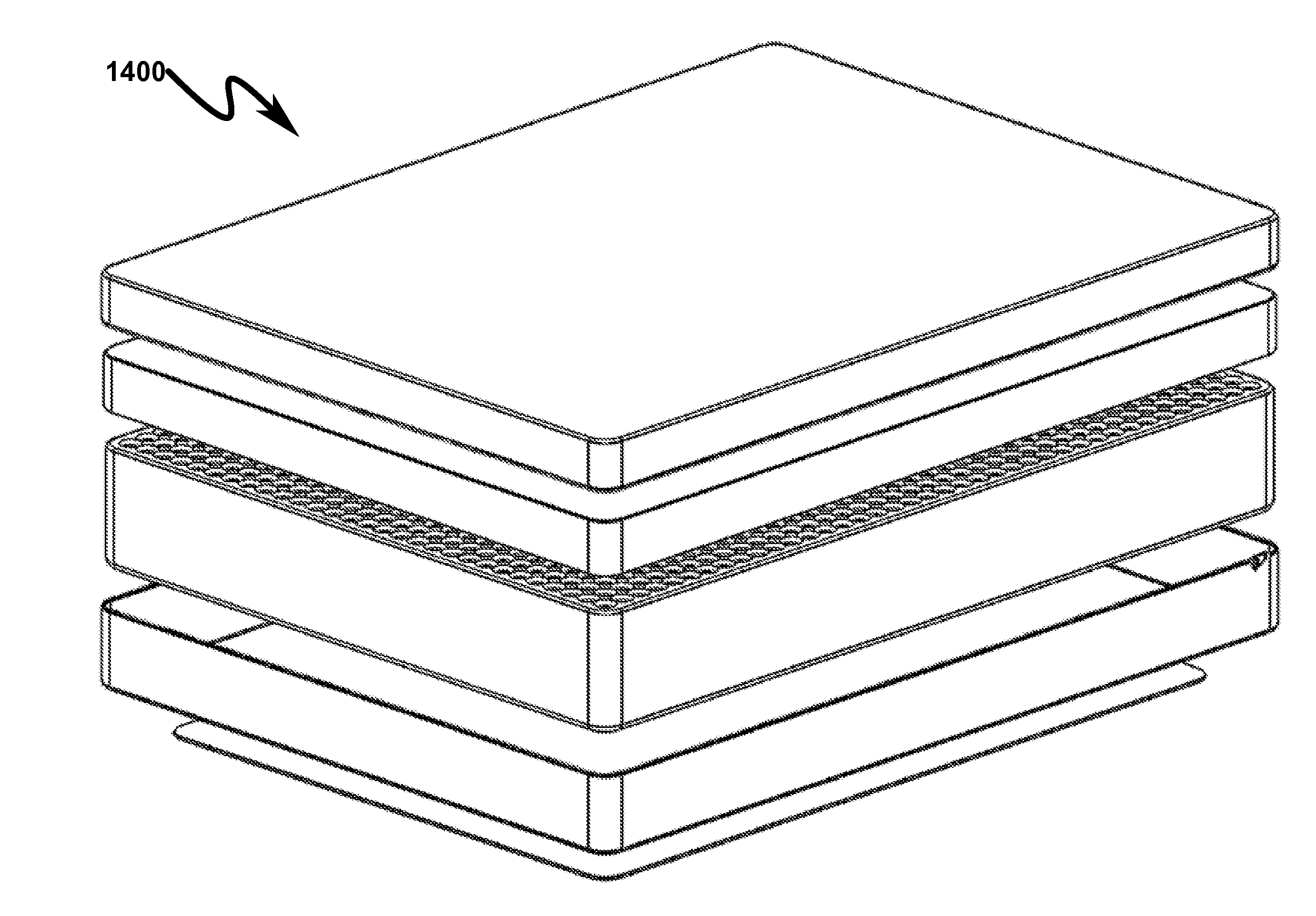
[0185]The present invention preferred exemplary method embodiment anticipates a wide variety of variations in the basic theme of implementation, but can be generalized as a field adjustable mattress method comprising:[0186](1) forming a static mattress core (SMC) comprising a mattress material in the shape of a substantially rectangular prism having a top surface, a bottom surface, a vertical thickness, and a perimeter;[0187](2) forming a mattress adjustment layer (MAL) comprising mattress material in the shape of a substantially rectangular prism having a top surface, a bottom surface, a vertical thickness, and a perimeter;[0188](3) positioning the MAL on top of the SMC to form a mattress stack;[0189](4) enveloping the mattress stack on the bottom and on a portion of the sides with a unitary bottom mattress cover (BMC);[0190](5) enveloping the mattress stack on the top and on a portion of the sides with a unitary top mattress cover (TMC);[0191](6)...


PUM


Abstract

A field adjustable mattress system/method allowing a baseline mattress configuration to be ergonomically modified after initial installation is disclosed. The baseline system generally consists of an optional bottom mattress support (BMS) connected to a bottom mattress cover (BMC) that partially envelops a static mattress core (SMC) from the bottom. A top mattress cover (TMC) completes the encapsulation of the foam mattress core and is attached to the BMC using top/bottom mattress cover zippers (MCZ). Field adjustment of the mattress system is accomplished by inserting one or more mattress adjustment layers (MAL) between the top of the SMC and the TMC and inserting an adjustment border panel (ABP) via the MCZ between the TMC and the BMC. The MAL may comprise one or more layers and may be inserted using horizontally and/or split configurations to permit a variety of ergonomic combinations to be supported in a single mattress system.

Description

CROSS REFERENCE TO RELATED APPLICATIONSU.S. Provisional Patent Applications[0001]This application claims benefit under 35 U.S.C. §119 and incorporates by reference United States Provisional Patent Application for FIELD ADJUSTABLE MATTRESS SYSTEM AND METHOD by inventors Andrew Antony Prochazka and Samuel William Prochazka, filed electronically with the USPTO on May 1, 2015, with Ser. No. 62 / 155,790, EFS ID 22233242 confirmation number 1033, docket ANBED.0101P.[0002]This application claims benefit under 35 U.S.C. §119 and incorporates by reference United States Provisional Patent Application for SYSTEM AND METHOD FOR MUTABLE MATTRESS by inventors Andrew Antony Prochazka and Samuel William Prochazka, filed electronically with the USPTO on Oct. 10, 2014, with Ser. No. 62 / 062,498, confirmation number 5036.PARTIAL WAIVER OF COPYRIGHT[0003]All of the material in this patent application is subject to copyright protection under the copyright laws of the United States and of other countries. ...

Claims


Application Information

Patent Timeline
IPC IPC(8): A47C31/12A47C31/00A47G9/04
CPCA47C31/12A47C31/001A47C31/00A47G9/04A47C27/064A47C27/085A47C27/144A47C27/146A47C27/148A47C27/15A47C31/123A47C31/105
Inventor PROCHAZKA, ANDREW ANTONYPROCHAZKA, SAMUEL WILLIAM
Owner PROCHAZKA ANDREW ANTONY
Why Eureka
Try Eureka