Compressor of Axial Turbine Engine with Contra-Rotating Rotor

a technology of compressor and axial turbine engine, which is applied in the direction of motors, engine fuctions, air transportation, etc., can solve the problems of difficult production precision, heavy and bulky, and particularly complex turbine engines

Active Publication Date: 2016-04-14
TECHSPACE AERO
View PDF15 Cites 31 Cited by
  • Summary
  • Abstract
  • Description
  • Claims
  • Application Information

AI Technical Summary

Problems solved by technology

However such a turbine engine is particularly complex.
This arrang

Method used


Image

  • Compressor of Axial Turbine Engine with Contra-Rotating Rotor
  • Compressor of Axial Turbine Engine with Contra-Rotating Rotor
  • Compressor of Axial Turbine Engine with Contra-Rotating Rotor

Examples


Embodiment Construction

[0012]The present application aims to overcome at least one of the problems posed by the prior art. The present application also aims to improve the efficiency of the turbine engine with a fan linked to a compressor via an epicyclic reducing gear. More precisely, the present application also aims to optimise the compression rate and compactness of a compressor.

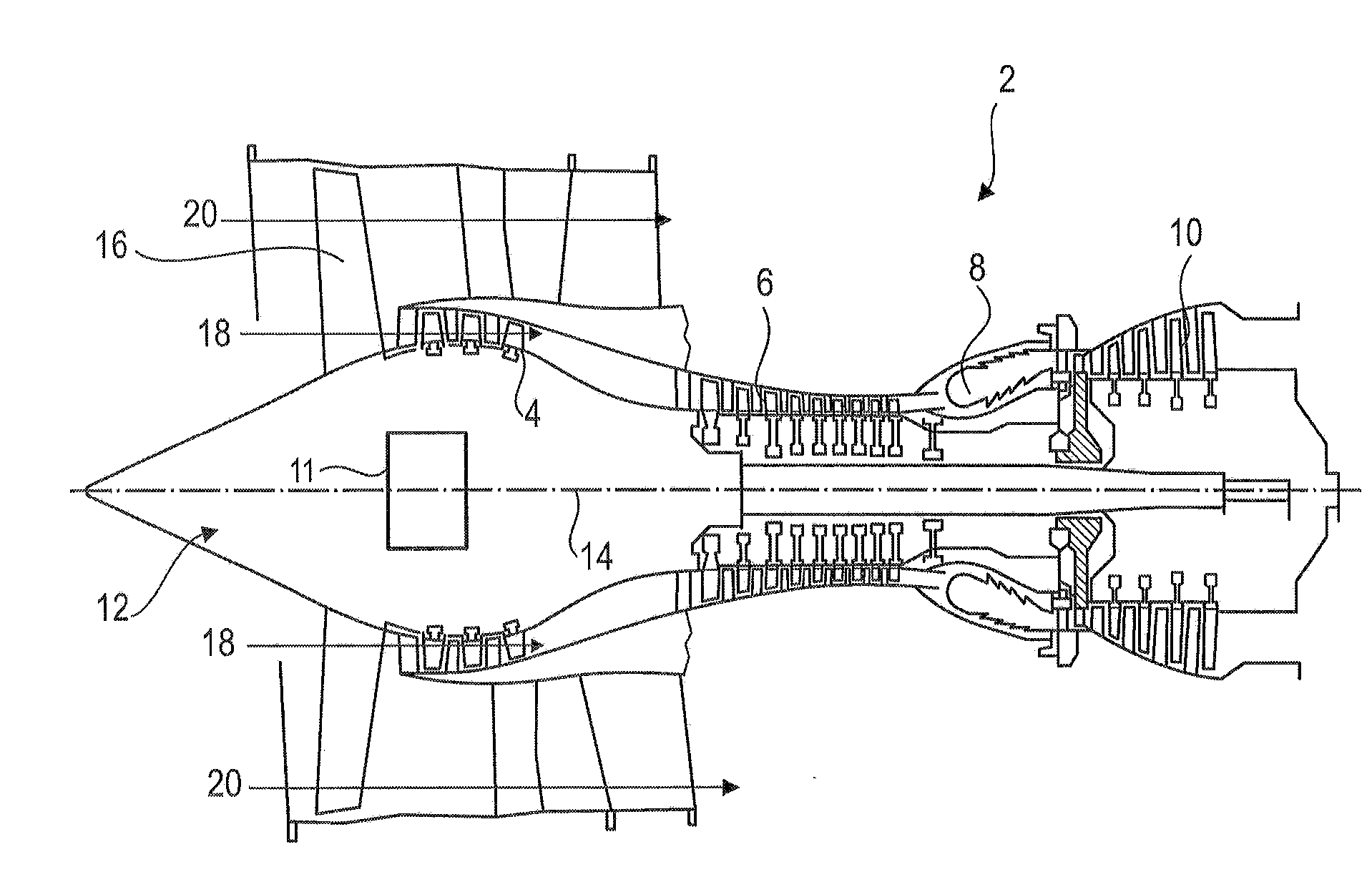
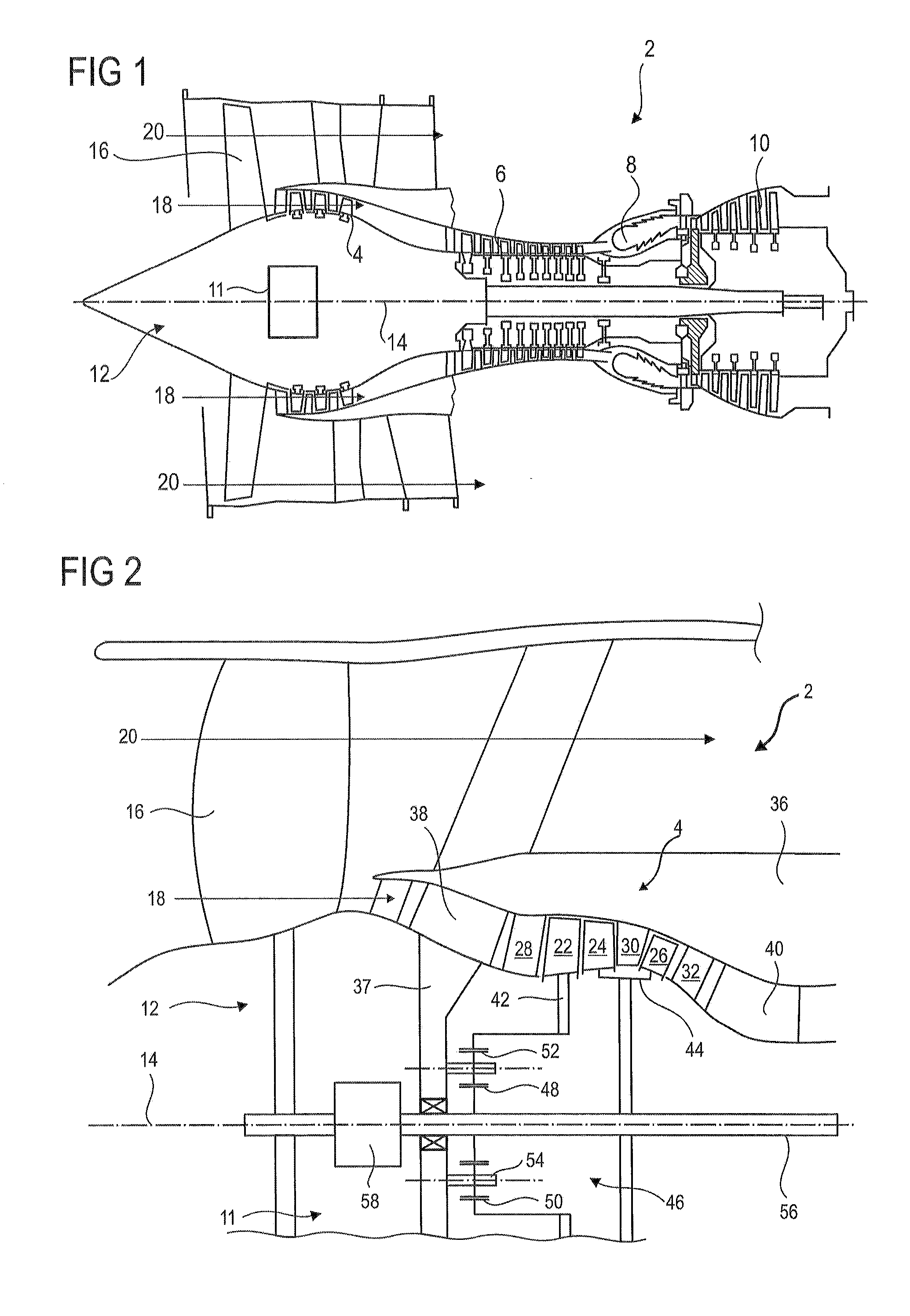
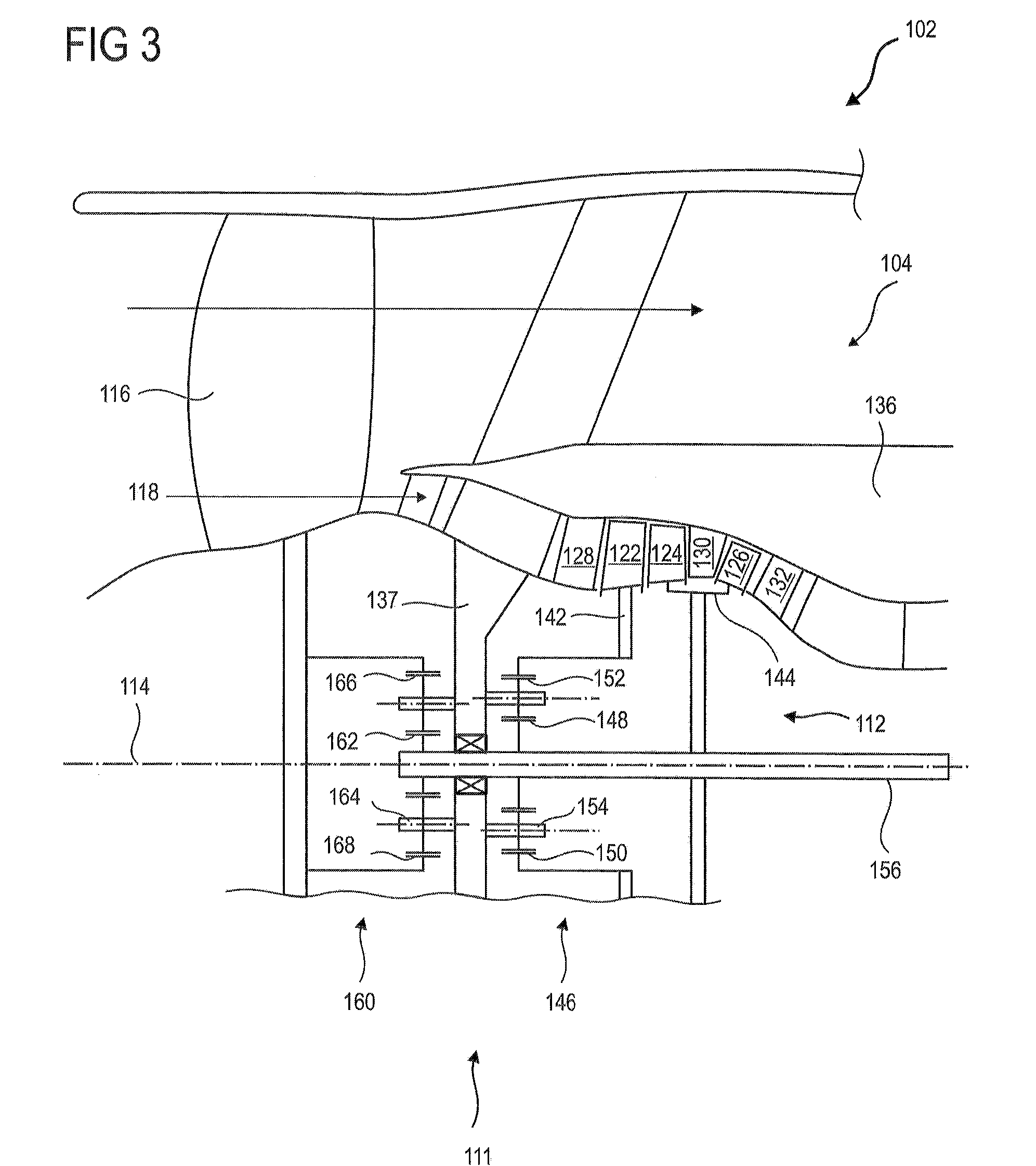
[0013]The present application also discloses an axial turbine engine such as a turbojet comprising a fan, a compressor fitted with a rotor with at least two annular rows of rotor blades, of which two rows are counter-rotating, an epicyclic reducing gear connecting the fan to the compressor rotor and connecting the counter-rotating rows, which is distinguished in that it also comprises an annular row of stator vanes arranged between two rows of rotor blades so as to straighten the flow between the two rows of rotor blades.

[0014]According to an advantageous embodiment of the present application, the row of stator vanes is arrang...


PUM


Abstract

The present application relates to an axial turbine engine with a turbine, a low-pressure compressor, and a fan. The turbine drives the compressor and the fan via a plurality of epicyclic reducing gears. The rotor of the compressor includes upstream a disc with a row of vanes and downstream a drum with a plurality of rows of vanes. The disc and the drum are connected to different parts of the epicyclic reducing gears, so as to be counter-rotating. The turbine engine includes a row of stator vanes arranged between two rows of rotor blades of the drum of the compressor, so as to straighten the flow and improve the efficiency. The turbine engine includes at least two epicyclic reducing gears, so that the vane rows of the drum turn faster than that downstream, which itself turns faster than the fan.

Description

[0001]This application claims priority under 35 U.S.C. §119 to Belgium Patent Application No. 2014 / 0740, filed 9 Oct. 2014, titled “Compressor of Axial Turbine Engine with Contra-Rotating Rotor,” which is incorporated herein by reference for all purposes.BACKGROUND[0002]1. Field of the Application[0003]The present application relates to an axial turbine engine fitted with a transmission. More precisely, the present application relates to a turbojet having a fan, a compressor, and an epicyclic train.[0004]2. Description of Related Art[0005]In order to modulate the rotation speed of the fan, a turbojet is provided with an epicyclic train. It allows the rotor of the low-pressure compressor to be decoupled from the fan, which eliminates technological constraints. The rotation speed of the fan is reduced relative to the compressor rotor, which is advantageous for turbine engines with a high dilution rate, combining a large fan and a compressor of reduced diameter. This technology becomes...

Claims


Application Information

Patent Timeline
IPC IPC(8): F02C3/10F02C7/36
CPCF02C3/10F05D2260/40F05D2220/32F02C7/36F02C3/067F02C3/107F02K3/06F04D19/024F05D2260/40311Y02T50/60F02C3/073F02K3/072
Inventor HIERNAUX, STEPHANE
Owner TECHSPACE AERO
Why Eureka
Try Eureka