Cable assembly

a cable and connector technology, applied in the direction of connection contact member materials, coupling device connections, instruments, etc., can solve the problems of difficult design of compact connectors, impedance discontinuities, attenuation, etc., and achieve the effect of stable and consistent signal characteristics

Active Publication Date: 2016-04-14
SAMTEC
View PDF4 Cites 71 Cited by
  • Summary
  • Abstract
  • Description
  • Claims
  • Application Information

AI Technical Summary

Benefits of technology

[0011]To overcome the problems described above, preferred embodiments of the present invention prov

Problems solved by technology

First, the pogo pins are relatively long.
Because pogo pins are relatively long, it is difficult to design a compact connector.
Also, the length of the pogo pins often causes significant portions of the pogo pins to be unshielded, which results in impedance discontinuities, attenuation, and low signal integrity.
Second, pogo pins are expensive because of the difficulties in their manufacturing and tight tolerances for many of the components of the pogo pins.
Third, the total downward force required to engage all of the pogo pins with the mating circuit board is quite large due to variances in the dimensions of the pogo pins, particularly the exposed length of the pogo pin which requires the spring to have a high spring constant.
Fourth, it is difficult to ensure proper impedance matching of the connectors due to unshielded portions of the pogo pins and variances in the dimensions of the pogo pins.
Fifth, convent

Method used


Image

  • Cable assembly
  • Cable assembly
  • Cable assembly

Examples


Embodiment Construction

[0040]Preferred embodiments of the present invention will now be described in detail with reference to FIGS. 1 to 18. Note that the following description is in all aspects illustrative and not restrictive and should not be construed to restrict the applications or uses of the present invention in any manner.

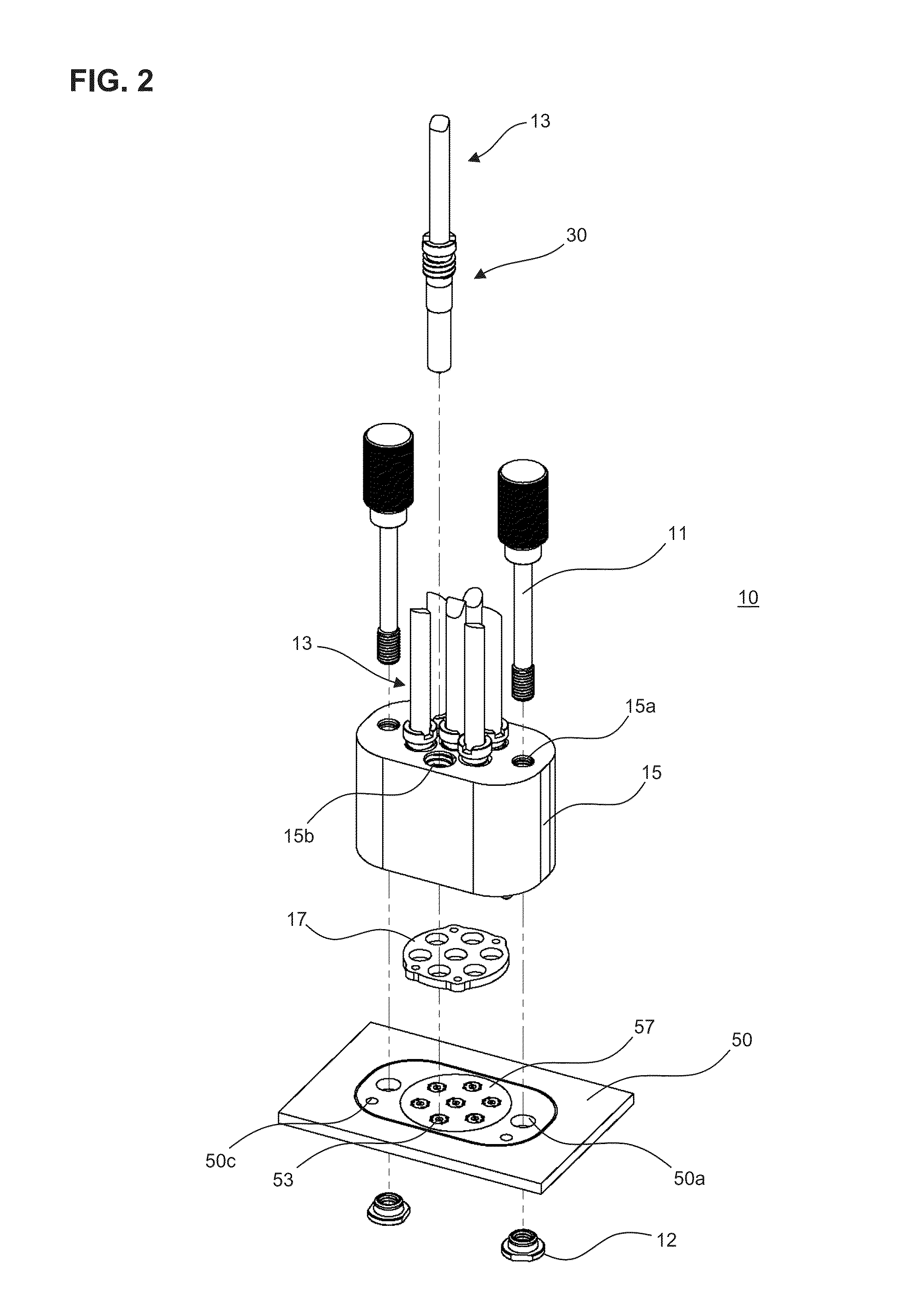
[0041]FIGS. 1 to 5 show a coaxial connector 10 in accordance with a first preferred embodiment of the present invention, and FIGS. 6 to 10 show a coaxial contact 30 and a coaxial cable 13. FIGS. 11A and 11B are top and bottom planar views of the substrate according to the first preferred embodiment of the present invention.

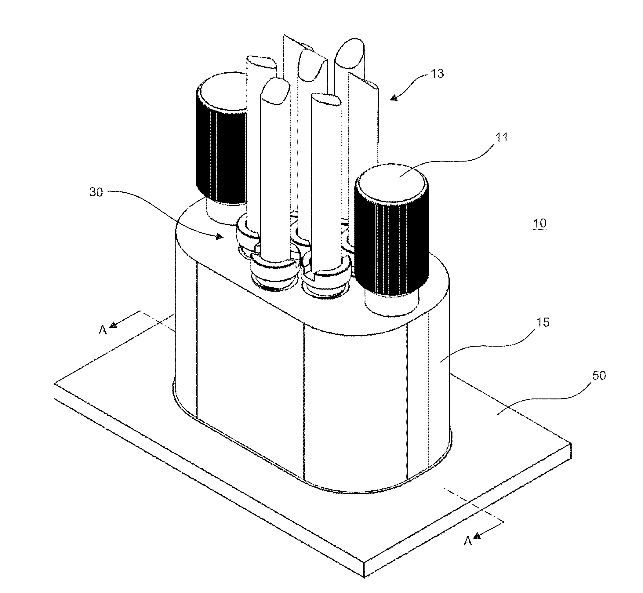
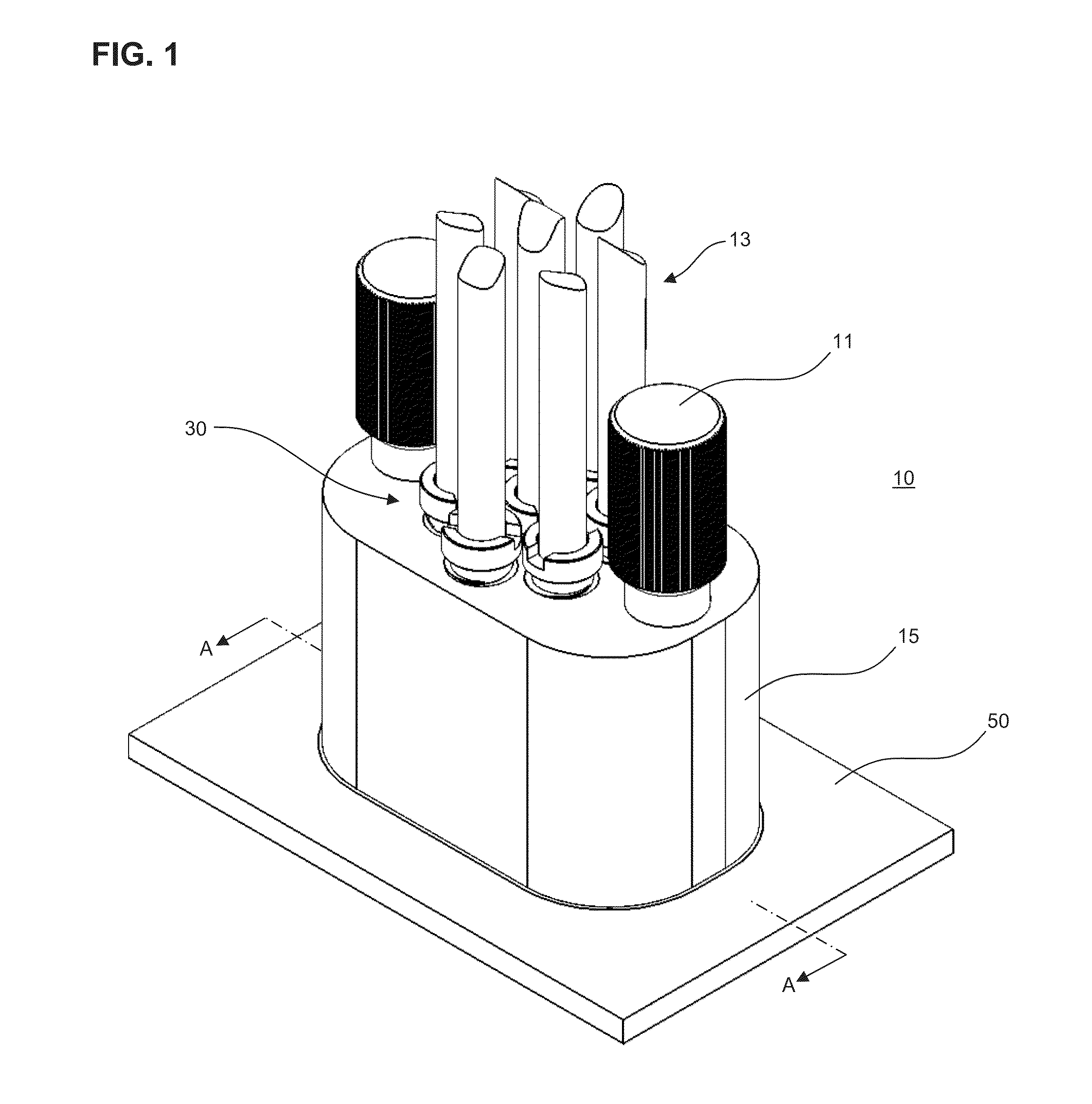
[0042]As shown in FIGS. 1 to 5, the coaxial connector 10 includes coaxial cables 13, coaxial contacts 30, and a connector body 15.

[0043]FIG. 1 is a perspective view of the coaxial connector 10. The connector body 15 of the coaxial connector 10 is attached to a substrate 50. The substrate 50 is preferably a printed circuit board, but other suitable substrates co...


PUM


Abstract

A connector includes a connector body including a hole, a contact disposed in the hole and arranged such that, when the connector is connected to a substrate, the contact is connected to a corresponding electrical pad on the substrate, a conductive elastomeric interface arranged such that, when the connector is connected to the substrate, the conductive elastomeric interface is between the connector body and the substrate, and a cable connected to the contact. The contact includes a ground ferrule and a locking ferrule arranged to mate with the hole, and the hole of the connector body and the locking ferrule are at least partially threaded. When the connector is connected to the substrate and when the locking ferrule is threaded with the hole, the ground ferrule contacts at least one of the conductive elastomeric interface and the upper surface of the substrate.

Description

BACKGROUND OF THE INVENTION[0001]1. Field of the Invention[0002]The present invention relates to electrical connectors. More specifically, the present invention relates to pogo pin-type coaxial and twinaxial connectors.[0003]2. Description of the Related Art[0004]One known connector used with automatic testing equipment includes a sub-connector that has pogo pins soldered to both sides of a circuit board. Sub-connectors are arranged into an array to form the connector. Pogo pins include a socket, a pin that is partially disposed in the socket, and a spring disposed in the socket that pushes the pin away from the socket. This arrangement allows the pogo pins to travel within the socket.[0005]Conventional pogo pins suffer from several drawbacks. First, the pogo pins are relatively long. Because pogo pins are relatively long, it is difficult to design a compact connector. Also, the length of the pogo pins often causes significant portions of the pogo pins to be unshielded, which result...

Claims


Application Information

Patent Timeline
IPC IPC(8): H01R9/05G01R1/04G01R1/067
CPCH01R9/0527G01R1/0416G01R1/067H01R11/18H01R13/2421H01R2201/20H01R9/0518H01R12/714H01R13/2414G01R1/06722H01R24/56
Inventor SANTOS, ROBERT MARINEHOFFMAN, JON REINERELLIS, TRAVIS SCOTTOUYANG, WILLIAM CHIENG
Owner SAMTEC
Why Eureka
Try Eureka