Catheter assembly

Active Publication Date: 2016-04-21
B BRAUN MELSUNGEN AG
View PDF9 Cites 44 Cited by
  • Summary
  • Abstract
  • Description
  • Claims
  • Application Information

AI Technical Summary

Benefits of technology

[0025]a second valve member preventing the flow of fluid through the chamber to or from the proximal end of the catheter hub, the second valve member being a two-way valve and openable to permit the flow of fluid through the chamber in the catheter hub in both a proximal and a distal direction.
[0071]In the protected position, the needle trap extends distally across the sharpened needle tip and prevents the needle moving in the distal direction relative to the needle guard assembly. The needle guard assembly further comprises means for limiting movement of the needle in the proximal direction relative to the needle guard assembly, so as to prevent the needle guard assembly from leaving the distal end of the needle. The limiting means may comprise a tether, for example extending between the needle hub and the needle guard housing. Preferably, the needle comprises a bulge, such as a crimp, in the distal end portion of the needle shaft spaced from the needle tip. The needle guard assembly, preferably the needle guard housing, comprises a proximal wall having an opening therein, the needle shaft extending through the opening in the proximal wall. The bulge in the needle shaft has a radial dimension that is larger than that of the opening in the proximal wall, such that the bulge and the distal end of the needle cannot pass through the opening. The region of the proximal wall surrounding the opening may be reinforced, for example by way of a metal ring or washer, to prevent the bulge in the needle shaft being inadvertently pulled through the proximal wall of the housing. This is particularly advantageous when the needle guard housing is formed from a relatively soft material, such as plastic. In the ready position, the bulge in the needle shaft preferably lies within the hollow catheter. When the bulge is non-circular it has the advantage of allowing blood to flow between the inside of the catheter and the outside of the needle, to provide the secondary blood flashback.

Problems solved by technology

The device of U.S. Pat. No. 5,098,405 does not permit fluids to be removed from the patient and only allows fluids to be infused to the patient through either the proximal end of the adapter hub or the port.

Method used


Image

  • Catheter assembly
  • Catheter assembly
  • Catheter assembly

Examples


Embodiment Construction

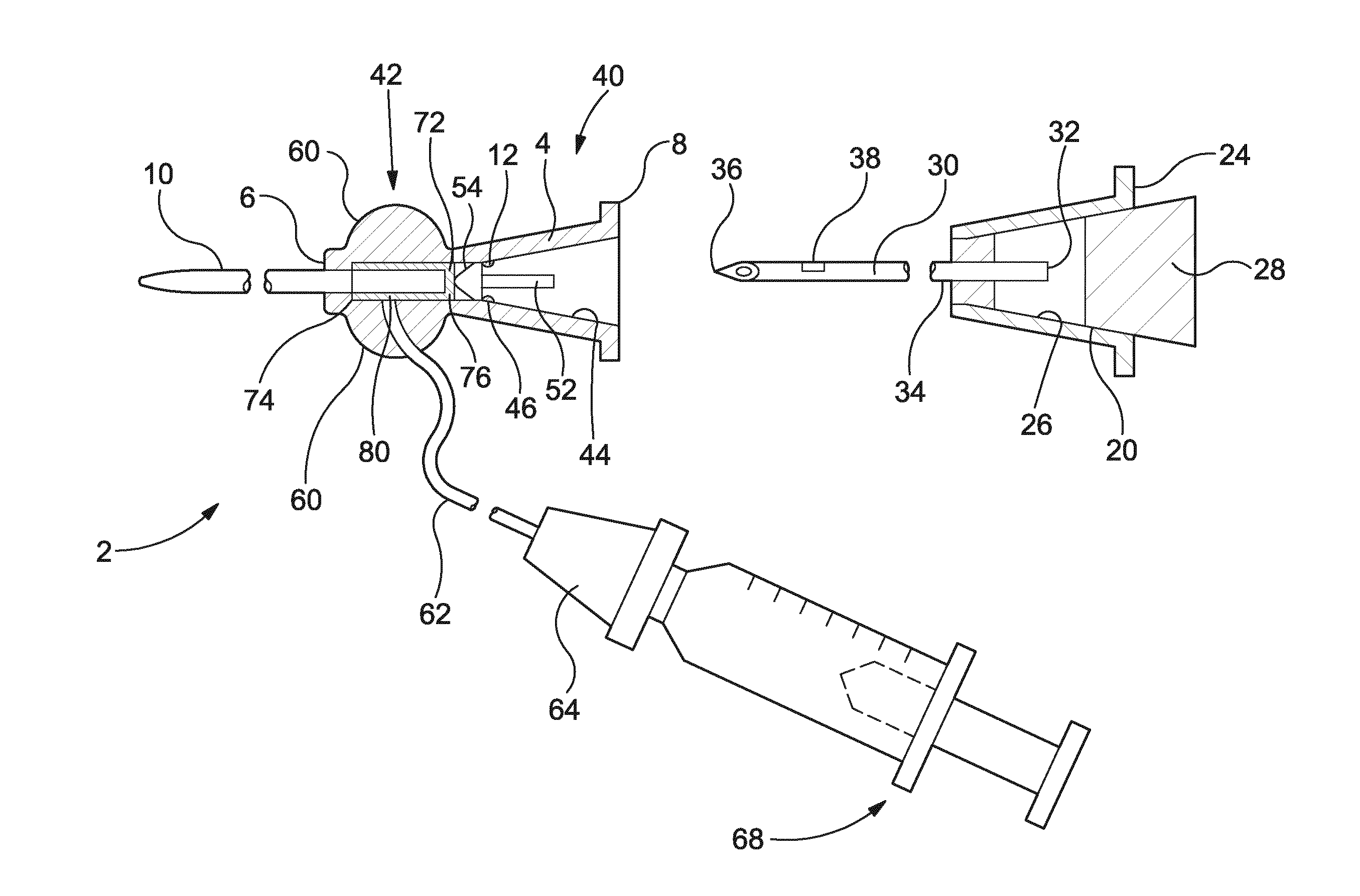
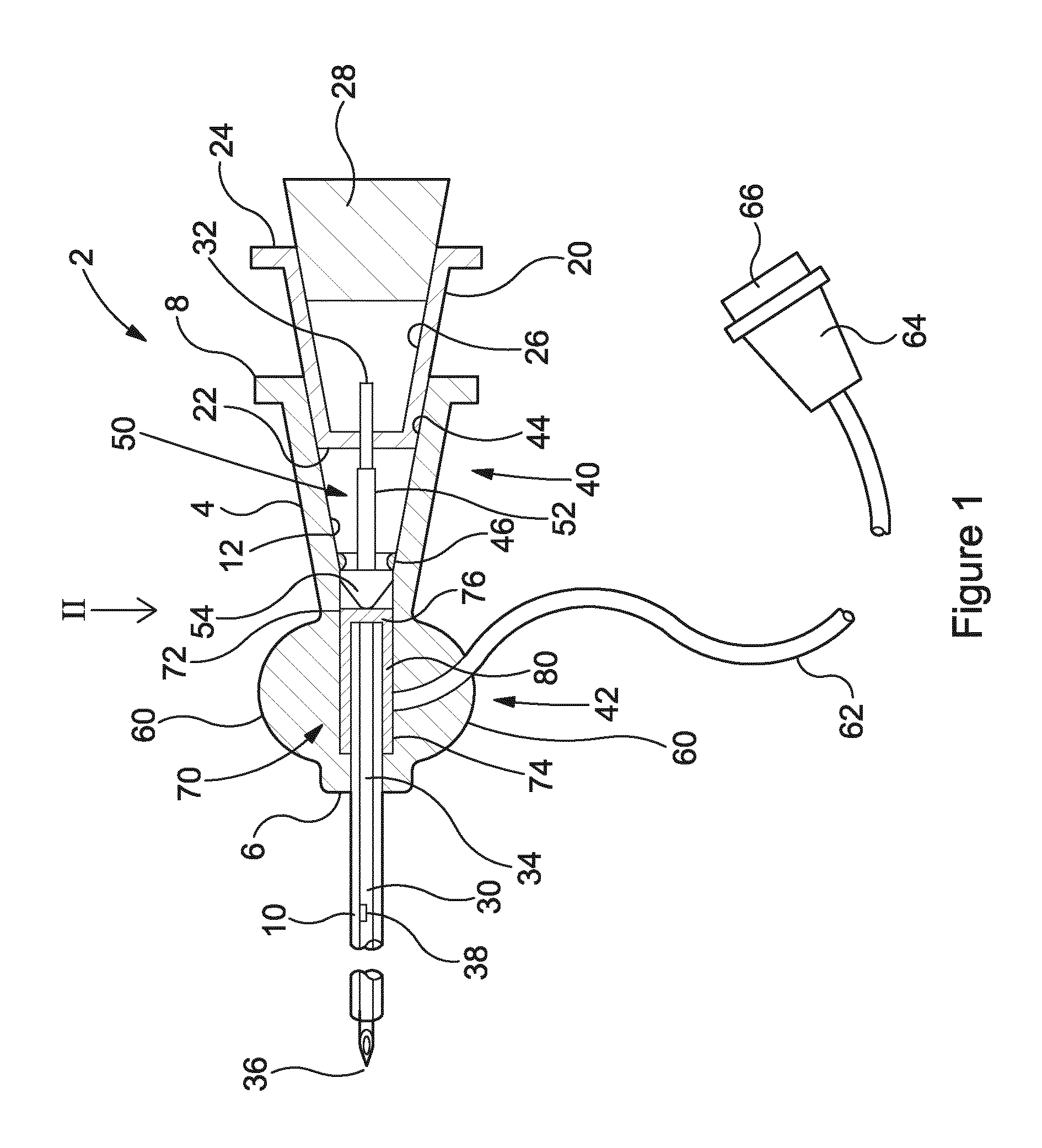
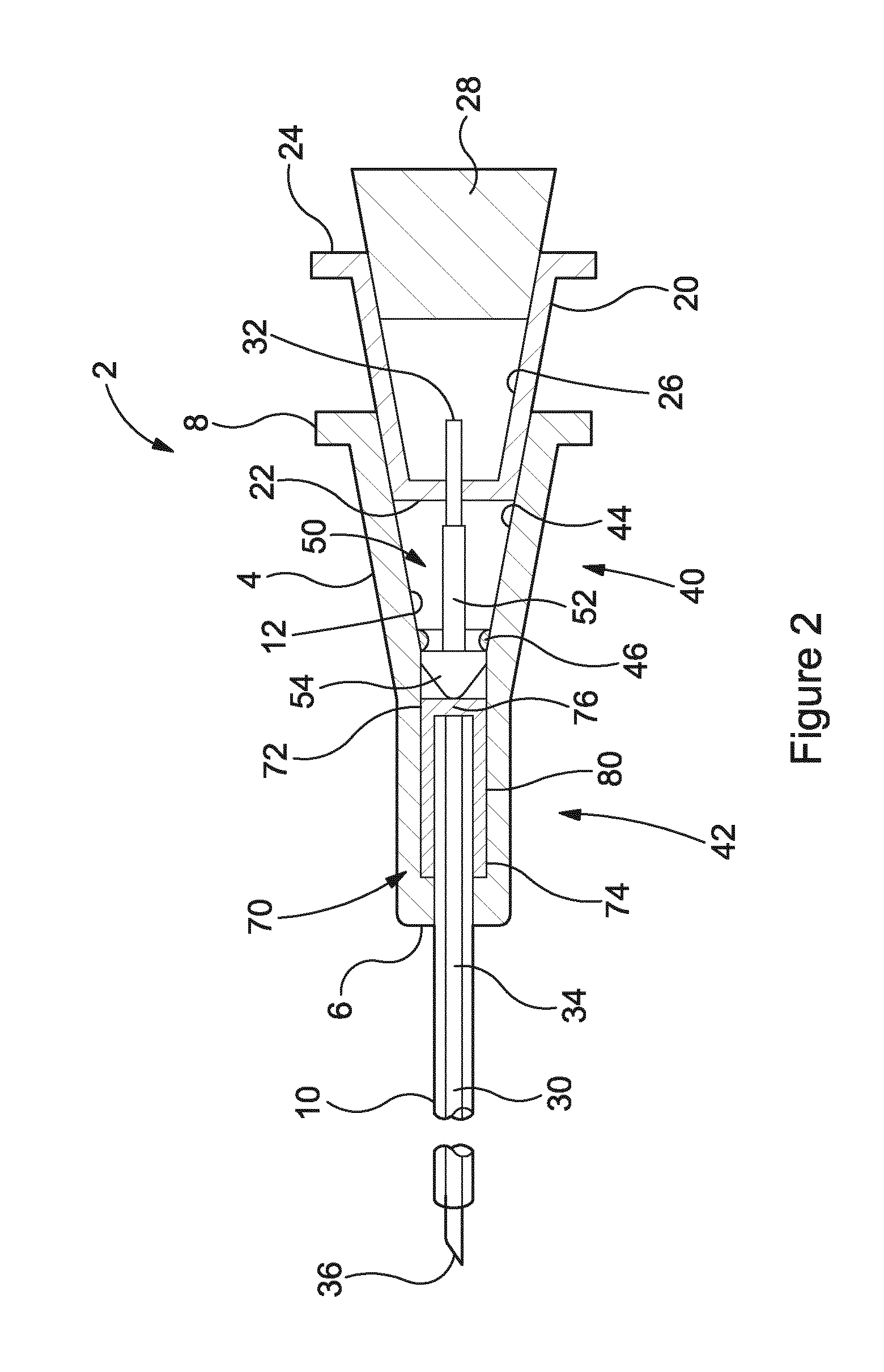
[0086]Referring to FIGS. 1 and 2, there is shown a device according to a first embodiment of the present invention, generally indicated as 2. The device 2 is shown in FIGS. 1 and 2 in a ready position. The device is shown in FIG. 3 in a retracted position, that is with the needle withdrawn in the proximal direction.

[0087]The device 2 comprises a catheter hub 4 having a distal end 6 and a proximal end 8. An elongate, hollow, tubular catheter 10 is connected to the catheter hub 4 and extends from the distal end 6 of the catheter hub, in known manner. The catheter hub 4 comprises an internal chamber 12. The internal chamber 12 is open at the proximal end 8 of the catheter hub 4 and communicates with the hollow catheter 10 at the distal end of the catheter hub. Details of the catheter hub are described in more detail below.

[0088]A generally cylindrical needle hub 20 has a distal end 22 and a proximal end 24. The needle hub 20 is formed with an internal chamber 26, the open proximal end ...


PUM


Abstract

A catheter assembly including a catheter hub being connectable to a device for the infusion or withdrawal of fluids; a hollow extension tube connected at its distal end to the catheter hub, the extension tube connectable at its proximal end to a device for infusing fluid into the chamber within the catheter hub; a valve assembly disposed within the chamber of the catheter hub having a first valve member and a second valve member preventing the flow of fluid through the chamber to or from the proximal end of the catheter hub. A needle guard assembly is also provided.

Description

[0001]The present invention relates to a catheter assembly, in particular to an intravenous catheter assembly.BACKGROUND OF THE INVENTION[0002]Intravenous (IV) catheters are used to access a vein of a patient, in particular for the provision of fluids to the patient or the removal of fluid, especially blood, therefrom. The IV catheter can be primed with a sterile solution to remove air from the device prior to puncturing the patient. This reduces the risks of the patient developing an air embolism.[0003]An IV catheter assembly comprises a catheter extending from the distal end of a catheter hub. A needle extends through the catheter hub and the catheter, such that the sharpened tip of the needle extends beyond the distal end of the catheter. A typical procedure for insertion of the catheter into the vein of the patient requires the healthcare worker to insert the sharpened needle tip and catheter into the patient to locate the vein. Once the needle tip is located in the vein, the he...

Claims


Application Information

Patent Timeline
Patent Type & Authority Applications(United States)
IPC IPC(8): A61M25/06
CPCA61M25/0606A61M25/0625A61M25/0097A61M2039/062A61M2039/064A61M2039/066A61M25/0618A61M25/0693A61M39/22A61M5/36A61M39/24A61M2039/242
Inventor WOEHR, KEVIN
Owner B BRAUN MELSUNGEN AG
Why Eureka
Try Eureka