
Polishing articles and integrated system and methods for manufacturing chemical mechanical polishing articles

a technology of chemical mechanical polishing and manufacturing system, which is applied in the manufacture of tools, dough shaping, food shaping, etc., can solve the problems of reducing the film removal rate, reducing the life of the media, and differential surface roughness of the polishing surface of the polishing media

Active Publication Date: 2016-04-21
APPLIED MATERIALS INC
View PDF22 Cites 33 Cited by
  • Summary
  • Abstract
  • Description
  • Claims
  • Application Information

AI Technical Summary

Benefits of technology

The patent describes a system and method for manufacturing a polishing article for chemical mechanical polishing. The system includes a feed section, a take-up section, and a curing section. The polishing article has a composite pad body with a plurality of polishing features and one or more base features. The base features surround the polishing features to form a unitary body, and the composite pad body has a hardness greater than the hardness of the base material. The replacement supply roll for chemical mechanical polishing includes a rod with a polishing article wound thereon, and the polishing article also has a composite pad body with a plurality of polishing features and one or more base features. The technical effects include improved polishing efficiency and consistent quality.

Problems solved by technology

However, the polishing process results in “glazing” or smoothening of a polishing surface of the polishing media, which reduces film removal rate.
However, while the rotation and / or down force applied to the conditioning disk is controlled, the cutting action is relatively indiscriminate, and the abrasives may not cut into the polishing surface evenly, which creates a differential in surface roughness across the polishing surface of the polishing media.
As the cutting action of the conditioning disk is not readily controlled, the media life may be shortened.
Further, the cutting action of the conditioning disk sometimes produces large asperities in the polishing surface, along with pad debris.
While the asperities are beneficial in the polishing process, the asperities may break loose during polishing, which creates debris that, along with pad debris from cutting action, contributes to defects in the substrate.
However, control of the devices and systems (e.g., cutting action, down force, among other metrics) remain unsatisfactory and may be frustrated by the properties of the polishing media itself.
For example, properties such hardness and / or density of the pad media may be non-uniform, which leads to more aggressive conditioning on some portions of the polishing surface relative to other portions.

Method used


Image

  • Polishing articles and integrated system and methods for manufacturing chemical mechanical polishing articles
  • Polishing articles and integrated system and methods for manufacturing chemical mechanical polishing articles
  • Polishing articles and integrated system and methods for manufacturing chemical mechanical polishing articles

Examples


Embodiment Construction

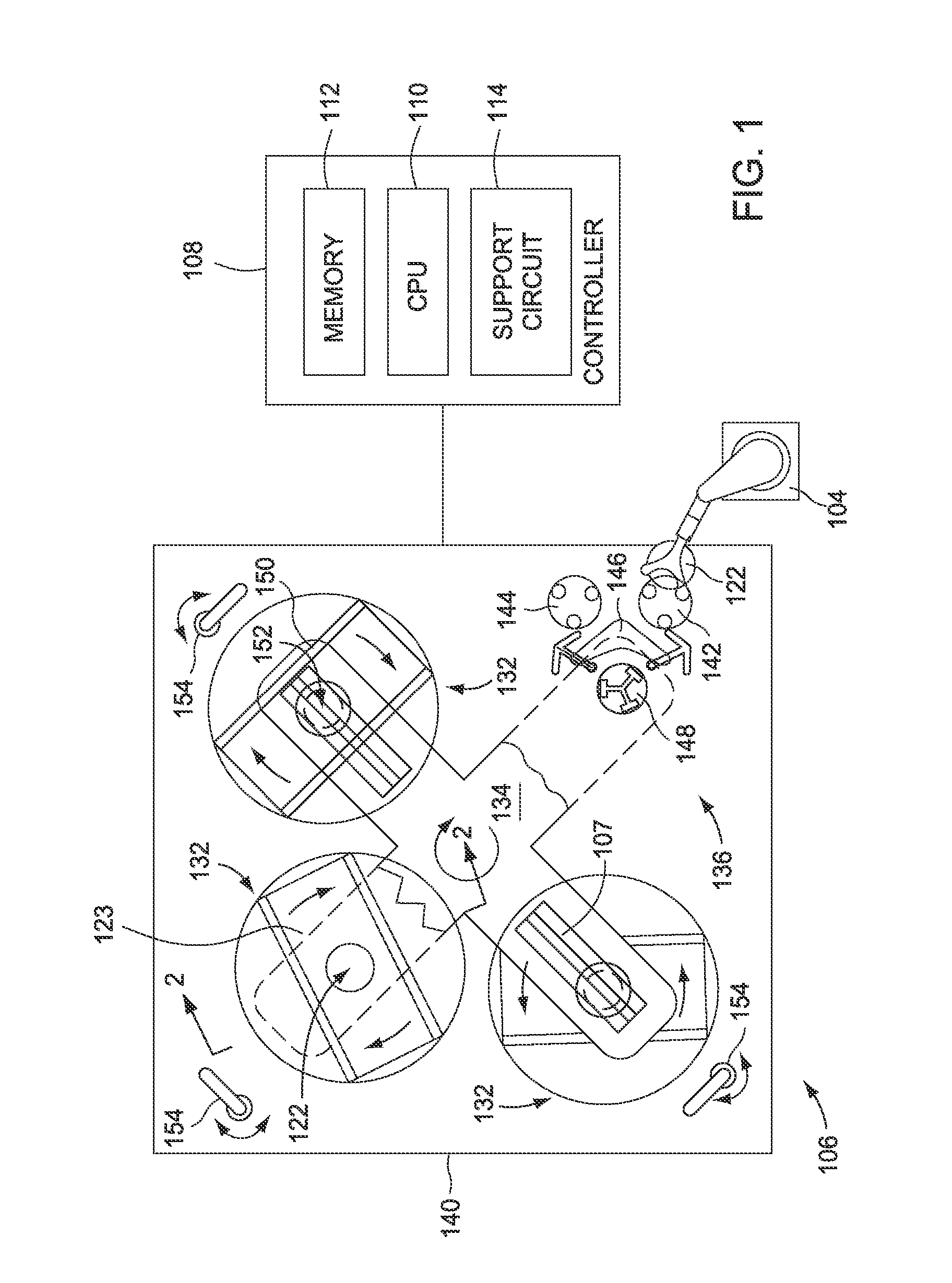
[0033]FIG. 1 depicts a plan view of a polishing module 106 which is a portion of a REFLEXION® Chemical Mechanical Polisher, manufactured by Applied Materials, Inc., located in Santa Clara, Calif. Embodiments described herein may be used on this polishing system. However, one skilled in the art may advantageously adapt embodiments as taught and described herein to be employed on other chemical mechanical polishers produced by other manufacturers that utilize polishing material, and particularly polishing material in a roll format.

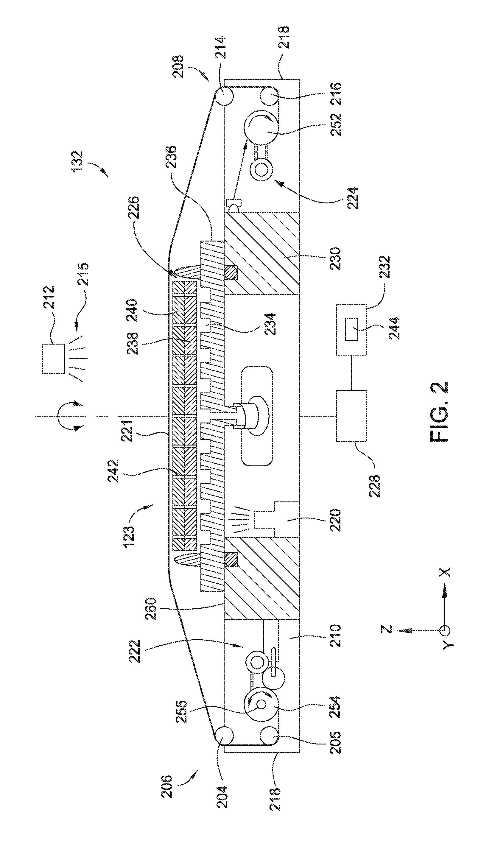
[0034]The polishing module 106 generally comprises a loading robot 104, a controller 108, a transfer station 136, a plurality of processing or polishing stations, such as platen assemblies 132, a base 140 and a carousel 134 that supports a plurality of polishing or carrier heads 152 (only one is shown in FIG. 1). Generally, the loading robot 104 is disposed proximate the polishing module 106 and a factory interface 102 (not shown) to facilitate the transfer ...


PUM

PropertyMeasurementUnit
mean diameteraaaaaaaaaa
sizesaaaaaaaaaa
thicknessaaaaaaaaaa

Abstract

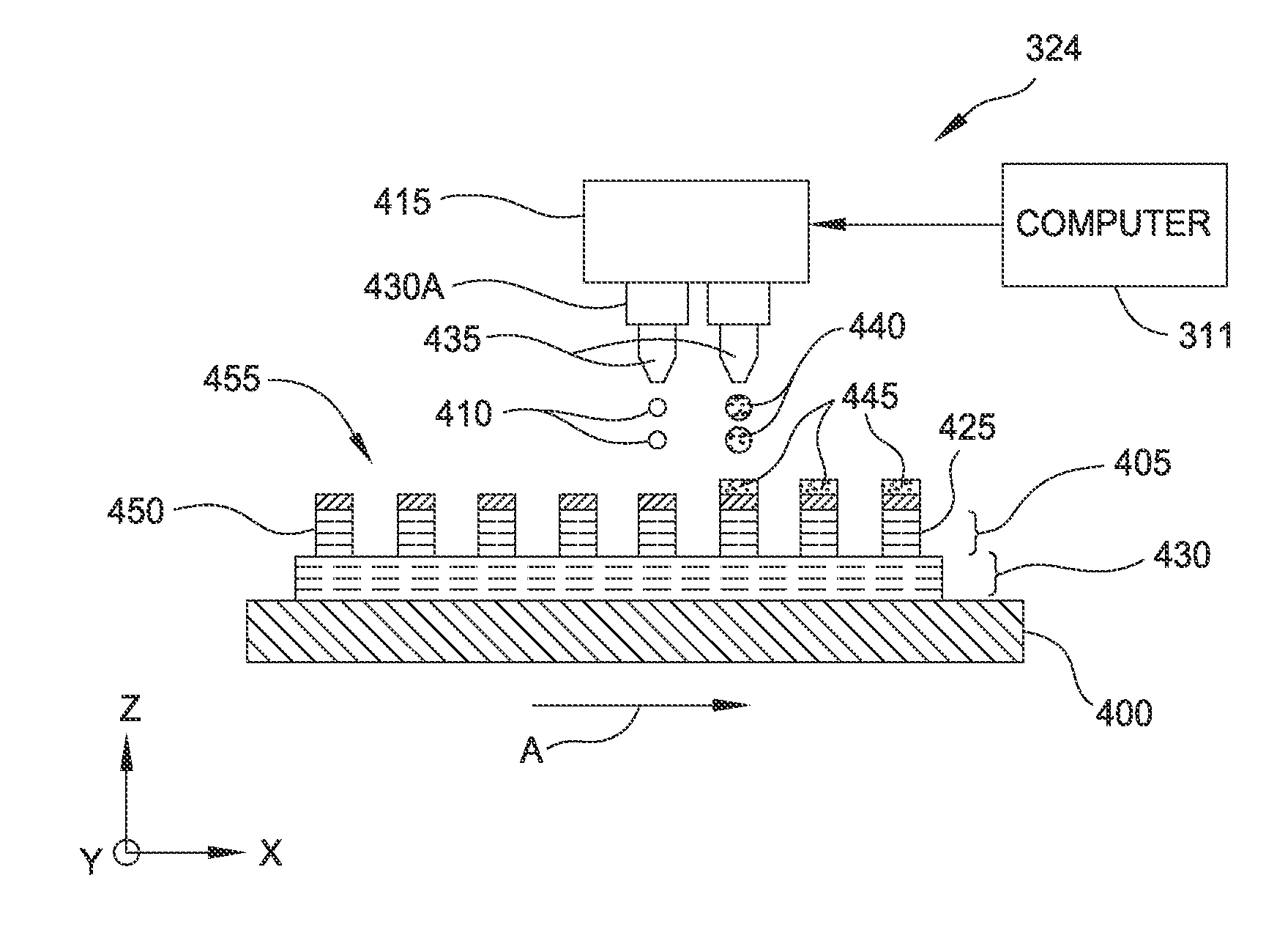
A polishing article manufacturing system includes a feed section and a take-up section, the take-up section comprising a supply roll having a polishing article disposed thereon for a chemical mechanical polishing process, a print section comprising a plurality of printheads disposed between the feed section and the take-up section, and a curing section disposed between the feed section and the take-up section, the curing section comprising one or both of a thermal curing device and an electromagnetic curing device.

Description

CROSS-REFERENCE TO RELATED APPLICATION:[0001]This application claims benefit of U.S. Provisional Patent Application Ser. No. 62 / 065,533 filed Oct. 17, 2014 (Attorney Docket No. 022351USL), which is hereby incorporated by reference herein.BACKGROUND[0002]1. Field[0003]Embodiments of the disclosure generally relate to an apparatus and method for chemical mechanical polishing of substrates or wafers, more particularly, to a polishing article manufacturing system and a method of manufacture of a polishing pad or polishing article for chemical mechanical polishing.[0004]2. Description of the Related Art[0005]In the fabrication of integrated circuits and other electronic devices on substrates, multiple layers of conductive, semiconductive, and dielectric materials are deposited on or removed from a feature side of a substrate. The sequential deposition and removal of these materials on the substrate may cause the feature side to become non-planar and require a planarization process, gener...

Claims


Application Information

Patent Timeline
Patent Type & Authority Applications(United States)
IPC IPC(8): B29C67/00B24B37/22B24B37/26
CPCB24B37/22B29C67/0085B29K2105/16B24B37/26B29L2031/736B29C67/0059B29K2995/007B33Y10/00B33Y30/00B33Y80/00B24B37/24H01L21/304H01L21/30625B24D11/001H01L21/67092B33Y70/00B29C64/112
Inventor KRISHNAN, KASIRAMANREDFIELD, DANIELPERRY, RUSSELL EDWARDMENK, GREGORY E.BAJAJ, RAJEEVREDEKER, FRED C.PATIBANDLA, NAG B.ORILALL, MAHENDRA C.FUNG, JASON G.
Owner APPLIED MATERIALS INC
Learn More