

Roof rack of collapsible tent and collapsible tent rack
- Summary
- Abstract
- Description
- Claims
- Application Information
AI Technical Summary
Benefits of technology
Problems solved by technology
Method used
Image

Examples
first embodiment
The First Embodiment
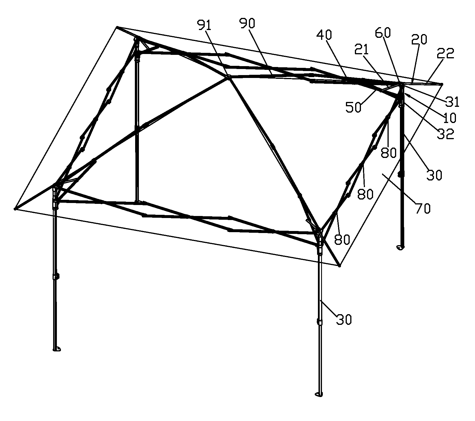
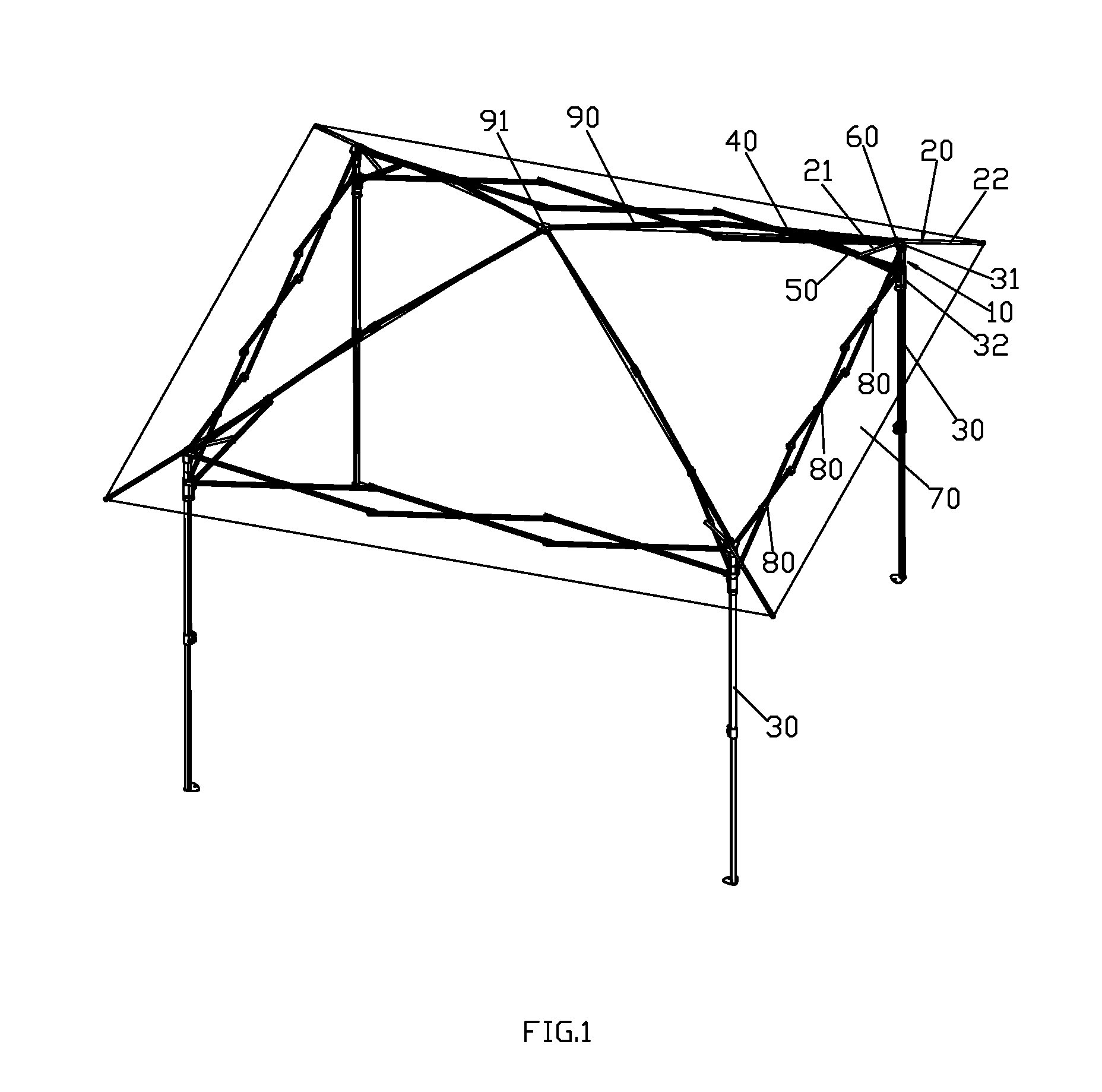
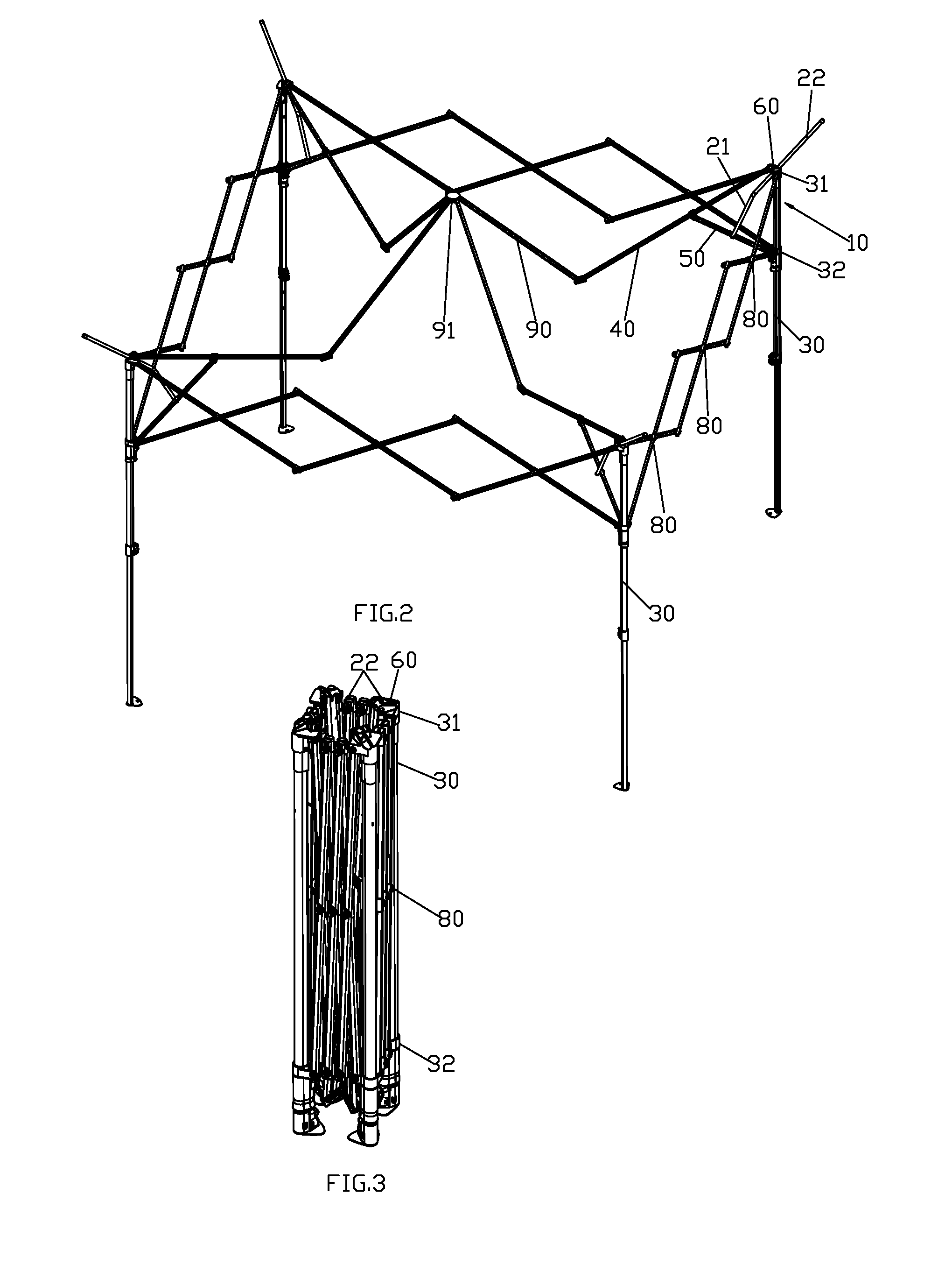
[0053]Referring to FIGS. 4-7, a roof rack 10 of a collapsible tent comprises a tent rack and roof poles 20.
[0054]The tent rack comprises stand columns 30, tent poles 40 and support poles 50, the top end of the stand column 30 is fixedly disposed with a top base 31, the stand column 30 is slidably disposed with a slide base 30 sliding up and down along the stand column 30; a lock position is disposed between the slide base 32 and the stand column 30, the lock position makes the slide base 32 kept in a position so that the tent rack keeps in unfolded state, if the lock position is released, the slide base 32 can slide up and down along the stand column The first end of the tent pole 40 is pivoted joint to the top base 31, the first end of the support pole 50 is pivoted joint to the slide base 32, the second end of the support pole 50 is pivoted joint to the central portion of the tent pole 40, the central portion means any position between the two ends, preferred t...
second embodiment
The Second Embodiment
[0061]Referring to FIGS. 8-11, the difference from the first embodiment is that: the roof rack 10 further comprises a slide element 64, the slide element 64 is pivoted joint to the top base 31, the slide way 60 is disposed to the slide element 64, the second straight section 22 of the roof pole 20 is coupled to the slide way 60 and slidably connected to the slide way 60, the relative movement of the slid way and the second straight section forms a translation structure. The intersection of the first straight section and the second straight section is corresponding to the slide way when the roof pole is unfolded, the corresponding means that the intersection rightly abuts against the slide element, the intersection is rightly near to the entrance of the slide way 60. In this embodiment, the slide way is pivoted joint to the top base, but not limited to this, as needed, it can also be pivoted joint to the portion of the stand column near to the top end or pivoted ...
third embodiment
The Third Embodiment
[0063]Referring to FIGS. 12-18, the difference from the first embodiment is that: the support pole 50 is slidably connected with a connecting base 51, the first end of the roof pole 20 is pivoted joint to the connecting base 51, the second end of the roof pole 20 is movably connected to the slide way 60 in stretching and retracting way to drive the roof pole 20 to unfold and fold. The slide way 32 slides up and down along the stand column 30 to drive the tent rack to unfold and fold, the tent rack, when unfolding or folding, drives the roof pole to stretch out or retract back.
[0064]The central portion of the support pole 50 is fixedly disposed with a limit protruding 52, the connecting base 51 slides between the slide way 32 and the limit protruding 52, when the roof pole 20 is unfolded, the connecting base 52 abuts against the limit protruding 53. Preferred, the lower portion of the support pole 50 is further disposed with a second limit protruding, the connecti...
PUM
 Abstract
Description
Claims
Application Information